Door Motor Communication Circuit
CHECK EACH DOOR MOTOR COMMUNICATION SIGNAL
Ignition switch ON.
Check output waveform between A/C auto amp. harness connector and ground with the oscilloscope.
+ − Output waveform A/C auto amp. Connector Terminal M50 16 Ground 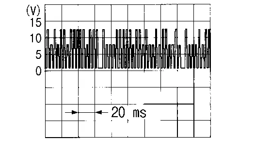
Is the inspection result normal?
YES>>GO TO 2.
NO>>GO TO 3.
CHECK EACH DOOR MOTOR COMMUNICATION SIGNAL CIRCUIT FOR OPEN
Ignition switch OFF.
Disconnect A/C auto amp. connector and intake door motor connector.
Check continuity between A/C auto amp. harness connector and intake door motor harness connector.
A/C auto amp. Intake door motor Continuity Connector Terminal Connector Terminal M50 16 M153 3 Yes
Is the inspection result normal?
YES>>Inspection End.
NO>>Repair harness or connector.
CHECK EACH DOOR MOTOR COMMUNICATION SIGNAL CIRCUIT FOR SHORT
Disconnect following connectors:
Air mix door motor LH
Air mix door motor RH
Mode door motor
Check continuity between A/C auto amp. harness connector and ground.
A/C auto amp. — Continuity Connector Terminal M50 16 Ground No
Is the inspection result normal?
YES>>Replace A/C auto amp. Refer to Removal and Installation.
NO>>Repair harness or connector.