Telescopic Sensor
DATA MONITOR
 CONSULT
Select “TELESCO PULSE” in “Data Monitor” mode of “AUTO DRIVE POS.”.
Check that the function operates normally according to the following conditions:
| Monitor item | Condition | Value | |
|---|---|---|---|
| TELESCO PULSE | Steering column | Operate (forward) | Change (decrease) |
| Operate (backward) | Change (increase) | ||
| Release | No change | ||
Is the inspection result normal?
YES>>Inspection End.
NO>>Perform diagnosis procedure. Refer to Diagnosis Procedure.
CHECK TELESCOPIC SENSOR SIGNAL
Ignition switch ON.
Check voltage signal between driver seat control unit connector and ground with oscilloscope.
| (+) | (–) | Condition | Voltage signal (Approx.) | ||
|---|---|---|---|---|---|
| Driver seat control unit | |||||
| Connector | Terminal | ||||
| B209 | 12 | Ground | Steering column | Operate | 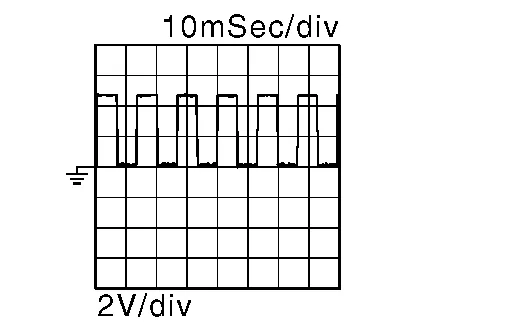 |
| Other than above | 0V or 5V | ||||
Is the inspection result normal?
YES>>Replace driver seat control unit. Refer to Removal and Installation.
NO>>GO TO 2.
CHECK TELESCOPIC SENSOR CIRCUIT
Ignition switch OFF.
Disconnect driver seat control unit and telescopic motor.
Check continuity between driver seat control unit harness connector and telescopic motor harness connector.
Driver seat control unit Telescopic motor Continuity Connector Terminal Connector Terminal B209 12 M94 4 Yes Check continuity between driver seat control unit harness connector and ground.
Driver seat control unit Ground Continuity Connector Terminal B209 12 No
Is the inspection result normal?
YES>>GO TO 3.
NO>>Repair or replace harness.
CHECK TELESCOPIC SENSOR POWER SUPPLY
Connect driver seat control unit.
Ignition switch ON.
Check voltage between telescopic motor harness connector and ground.
(+) (–) Voltage
(Approx.)Telescopic motor Connector Terminal M94 5 Ground Battery voltage
Is the inspection result normal?
YES>>GO TO 5.
NO>>GO TO 4.
CHECK TELESCOPIC SENSOR POWER SUPPLY CIRCUIT
Ignition switch OFF.
Disconnect automatic drive positioner control unit.
Check continuity between automatic drive positioner control unit harness connector and telescopic motor harness connector.
Automatic drive positioner control unit Telescopic motor Continuity Connector Terminal Connector Terminal M34 27 M94 5 Yes Check continuity between automatic drive positioner control unit harness connector and ground.
Automatic drive positioner control unit Ground Continuity Connector Terminal M34 27 No
Is the inspection result normal?
YES>>Replace automatic drive positioner control unit. Refer to Removal and Installation.
NO>>Repair or replace harness.
CHECK TELESCOPIC SENSOR GROUND CIRCUIT
Ignition switch OFF.
Disconnect automatic drive positioner control unit.
Check continuity between automatic drive positioner control unit harness connector and telescopic motor harness connector.
Automatic drive positioner control unit Telescopic motor Continuity Connector Terminal Connector Terminal M33 20 M94 3 Yes
Is the inspection result normal?
YES>>Replace telescopic motor. Refer to Exploded View.
NO>>Repair or replace harness.