Fault Location Tree
FT 1 ABS WARNING LIGHT DOES NOT COME ON FOR 3 SECONDS WHEN IGNITION IS SWITCHED ON
NOTE Only consult this customer complaint after a complete check with the XR25 tool.
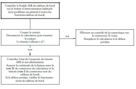
AFTER REPAIR Carry out a road test, then check with the XR25 tool.
FT 2 ABS WARNING LIGHT STAYS ON PERMANENTLY WHEN IGNITION IS ON (no fault declared by the XR25 tool)
INSTRUCTIONS Only consult this customer complaint after a full check with the XR25 tool.
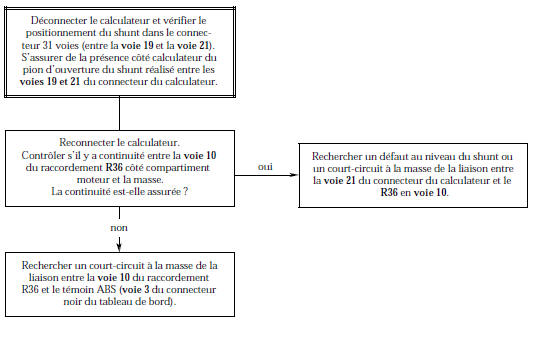
AFTER REPAIR Carry out a road test, then check with the XR25 tool.
FT 3 ABS WARNING LIGHT COMES BACK ON AFTER ENGINE START INTERMITTENT ABS WARNING LIGHT IN DRIVING
NOTE Only consult this customer complaint after a complete check with the XR2
Check the ECU supply voltage: 9.5 volts < correct voltage < 17.5 volts.If necessary, carry out the following operations:
- Check the battery charge (check the charging circuit if necessary).
- Check the tightness and condition of the battery terminals.
- Check the ABS earths (tightness of the two earth screws above the ABS unit).
Disconnect the ECU and check the condition of the connectors and the position of the jumper in the 31-way connector (between pin 19 and pin 21).
Check on the ECU side, the condition of the opening pin of this jumper.
AFTER REPAIR Carry out a road test, then check with the XR25 tool.
FT 4 LOCKING OF ONE OR MORE WHEELS
NOTE Only consult this customer complaint after a complete check with the XR25 tool.
REMINDER: Wheel lock on a vehicle fitted with ABS, or tyre squeal that the customer perceives as lock-up, may be a normal system reaction and must not systematically be considered a fault:
|
However, if wheel(s) are actually locking, raise the vehicle so that the wheels can be turned and check:
If the fault persists after these checks, replace the hydraulic unit. |
AFTER REPAIR Carry out a road test, then check with the XR25 tool.
FT 5 VEHICLE PULLING
NOTE Only consult this customer complaint after a complete check with the XR25 tool.
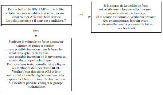
AFTER REPAIR Carry out a road test, then check with the XR25 tool.
FT 6 WEAVING
INSTRUCTIONS Only consult this customer complaint after a full check with the XR25 tool.
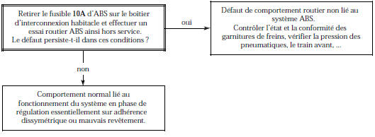
AFTER REPAIR Carry out a road test, then check with the XR25 tool.
FT 7 UNEXPECTED ABS OPERATION AT LOW SPEED AND LIGHT PEDAL EFFORT
Vibrations may be felt through the brake pedal, caused by normal system reactions in certain situations:- Driving over speed bumps.
- Tight bend with inside rear wheel lifted.
If the problem is different, check the speed sensor connectors (micro-breaks) and the air gaps.
AFTER REPAIR Carry out a road test, then check with the XR25 tool.
FT 8 UNEXPECTED ABS OPERATION ON POOR ROAD SURFACES
NOTE Only consult this customer complaint after a complete check with the XR25 tool.
On poor road surfaces, jolts and vibrations through the pedal, and squealing louder than on good road surfaces, are normal.This results in an impression of variable braking efficiency, which is to be considered normal.
AFTER REPAIR Carry out a road test, then check with the XR25 tool.
FT 9 UNEXPECTED ABS OPERATION WHEN SPECIAL EQUIPMENT IS USED (radio telephone, CB...)
NOTE Only consult this customer complaint after a complete check with the XR25 tool.
Check that the equipment causing the problem when in use is approved.Check that this equipment has been correctly installed without modifying the original wiring, in particular that of the ABS (connections to earth and to ABS + APC / AVC are not permitted).
AFTER REPAIR Carry out a road test, then check with the XR25 tool.
FT 10 INCREASED BRAKE PEDAL TRAVEL FOLLOWING A REGULATION PHASE (with a pedal that sinks when regulation starts)
NOTE Only consult this customer complaint after a complete check with the XR25 tool.
| Air ingress from the hydraulic unit regulation channels into the brake circuits. Bleed the circuits following the procedure given in the technical note, using the XR25 valise command modes. These command modes are described in the "help" chapter. After the repair, carry out a road test with ABS regulation. |
| If the fault persists, repeat the previous operation once or twice more. If the customer complaint is particularly pronounced and bleeding does not improve the condition, replace the hydraulic unit. |
AFTER REPAIR Carry out a road test, then check with the XR25 tool.
ALP 11 LONG BRAKE PEDAL
NOTE Only consult this customer complaint after a complete check with the XR25 tool.
Air present in the brake circuits.Carry out a conventional brake bleed, starting with the right rear brake, then left rear, left front, and finally right front.
Repeat the operation if necessary.
AFTER REPAIR Carry out a road test, then check with the XR25 tool.
ALP 12 BRAKE PEDAL VIBRATION
INSTRUCTIONS Only consult this customer complaint after a full check with the XR25 tool.
Normal feedback at the brake pedal during an ABS regulation phase.
AFTER REPAIR Carry out a road test, then check with the XR25 tool.
ALP 13 NOISE FROM PUMP, PIPING OR HYDRAULIC UNIT
NOTE Only consult this customer complaint after a complete check with the XR25 tool.
- Unit vibration: check the presence and condition of the insulating rubber mounts on the unit bracket.
- Pipe vibration: check that all pipes are correctly clipped into their retaining clips and that there is no contact between pipes, or between pipes and the bodywork.
To determine the source of the noise, you can use functions G03*, G04*, G05* and G06* of the XR25 valise (see the "help" chapter).
AFTER REPAIR Carry out a road test, then check with the XR25 tool.
ALP 14 ABS WARNING LIGHT DOES NOT COME ON, ECU DISCONNECTED
NOTE Only consult this customer complaint after a complete check with the XR25 tool.
Disconnect the ABS ECU.Check for the presence of the jumper between pin 19 and pin 21 of the ECU connector.
AFTER REPAIR Carry out a road test, then check with the XR25 tool.
ALP 15 NO COMMUNICATION WITH THE ABS ECU
NOTE Only consult this customer complaint after a complete check with the XR25 tool.
| Ensure the XR25 tester is not the cause of the fault by trying to communicate with an ECU on another vehicle. If the XR25 tester is not at fault and communication cannot be established with any other ECU on the same vehicle, a faulty ECU may be disturbing diagnostic lines K and L. Disconnect components one after another to locate this ECU. Check that the ISO interface is set to position S8, that you are using the latest XR25 cartridge version, and that the correct access code is entered. Check the battery voltage and carry out the necessary work to obtain a compliant voltage (9.4 volts < U battery < 17.4 volts). |
| Check the presence and condition of the ABS fuse in the passenger compartment interconnection box (10A). Check the ECU connector connection and the condition of its terminals. Check the connection and condition of the wiring at the R36 dashboard / ABS connector. Check the ABS earths (tightness of the two earth screws above the ABS unit). Check that the ECU is correctly supplied:
|
Check that the diagnostic socket is correctly supplied:
Check the continuity and insulation of the lines between the diagnostic socket and the ABS ECU:
|
| If communication still cannot be established after these checks, replace the ABS ECU. |
AFTER REPAIR Carry out a road test, then check with the XR25 tool.
Test yourself
A quick Renault Kangoo quiz: every answer comes with an explanation and a link to the manual page.