Powertrain
D7F engine
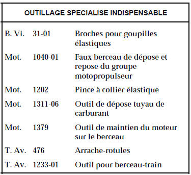
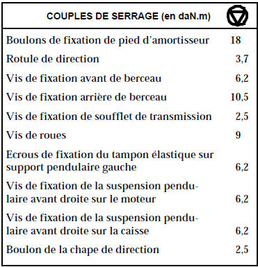
REMOVAL
Place the vehicle on a two-post lift.
Disconnect:
- the battery,
- the electrical connectors on the engine interconnection box and its surroundings.
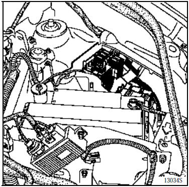
Drain:
- the cooling circuit (disconnect the lower radiator hose),
- the gearbox oil if necessary,
- the engine oil if necessary.
Remove:
- the battery,
- the wheels,
- the air intake duct,
- the upper radiator mountings,
- the expansion tank and secure it to the engine,
- the power steering reservoir, secure it to the engine.
Disconnect:
- the accelerator cable,
- the canister hose,
- the brake servo hose,
- the heater hoses,
- the oxygen sensor connector,
- the fuel pipes.
Remove:
- the shock absorber lower bolts,
- the steering clevis bolt.
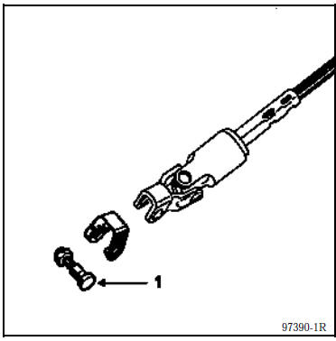
SPECIAL PROCEDURES FOR VEHICLES FITTED WITH DRIVER AIRBAG
CAUTION
To avoid any risk of damaging the clock spring, observe the following instructions:
- Before disconnecting the steering column from the steering rack, the steering wheel MUST be locked in the straight-ahead position using a "steering wheel lock" tool for the entire duration of the operation.
- Any doubt about the correct centring of the clock spring requires removal of the steering wheel in order to apply the centring method described in the Technical Note covering the 2nd generation airbag.
REMINDER: in this case, only trained qualified personnel may carry out the work.
Remove:
- the two cradle reinforcements,
- the body-side earth strap bolt,
- the exhaust downpipe nuts.
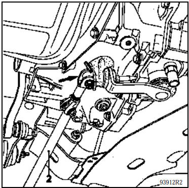
Disconnect the gear selector linkage:
- at the gearbox output lever after releasing the protective boot,
- at the gear lever after removing the centre heat shield.
Pull the rod (2) towards the rear of the vehicle.
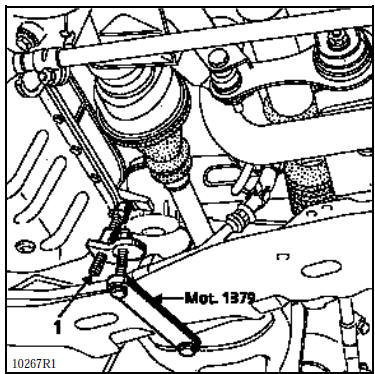
Fit Mot. 1379 to the cradle and, using the threaded rod (1), relieve the right-hand engine mounting.
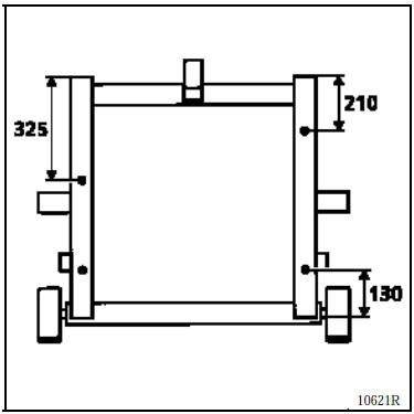
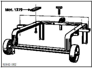
Attach Mot. 1040-01 under the cradle, having first fitted the Mot. 1379 shims to this tool.
Place a wooden wedge between the gearbox and the cradle.
Drilling diagram for Mot. 1040-01 (dimensions in mm).
Remove:
- the gearbox pendulum mount securing nut, then, using a bronze drift, strike to release the stud from the pendulum suspension mounting,
- the engine pendulum mount bolts to the engine.
Lower the lift until the tool contacts the ground.
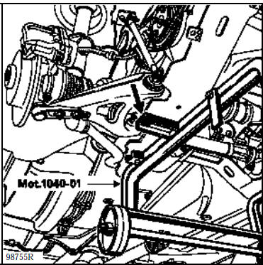
Remove the four cradle mounting bolts.
Remove the powertrain by raising the body.
REFITTING (Specific points)
Use tool T. Av. 1233-01 to position the powertrain relative to the body.
Refit in the reverse order of removal.
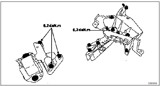
Tighten the pendulum mount fixing bolts and nuts to torque.
Apply RHODORSEAL 5661 to the transmission dowel hole.
Press the brake pedal several times to bring the pistons into contact with the brake pads.
Carry out:
- a gearbox oil top-up (if necessary),
- an engine oil top-up (if necessary),
- a coolant top-up and bleeding of the cooling system (see chapter 19).
E7J Engine
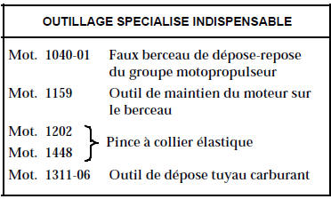
REMOVAL
Position the vehicle on a two-post lift.
Remove the battery.
Drain:
- the cooling circuit via the lower radiator hose,
- the gearbox and engine if necessary.
Remove:
- the bonnet,
- the front wheels,
- the cradle-to-body tie rods,
- the mounting bolts (1), spread the brake calipers as shown in the diagram below and secure them to the suspension springs,
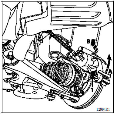
- the shock absorber base bolts,
- the exhaust heat shield and the gear selector linkage at the lever and gearbox end,
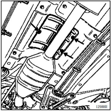
- the exhaust clamp between the catalytic converter and the intermediate pipe,
- the earth strap on the gearbox,
- the front bumper,
- the air filter inlet sleeve,
- the injection ECU bracket, having disconnected the 55-way connector and that of the impact sensor.
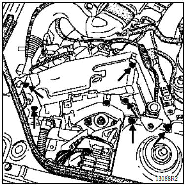
Disconnect:
- the wiring connector and the hoses on the thermostat housing,
- the hoses on the expansion tank,
- the brake servo hose,
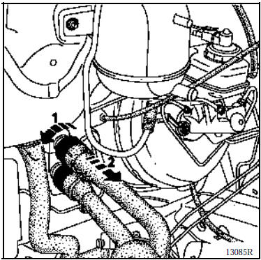
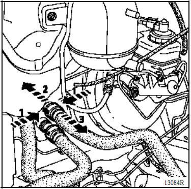
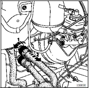
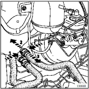
- the heater hoses (two fitting types exist, disconnect according to the diagrams below),
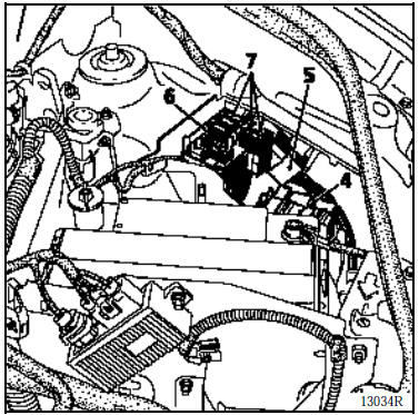
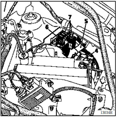
- the relay board (4), the connector (5) and the fuse holder (6) after removing the fuse holders (7),
- the hose on the canister,
- the fuel supply and return pipes using Mot. 1311-06, after removing the trim cover.
- the accelerator and clutch cables.
Unclip the power steering reservoir and place it on the engine.
Remove:
- the upper radiator mountings and tie it to the engine,
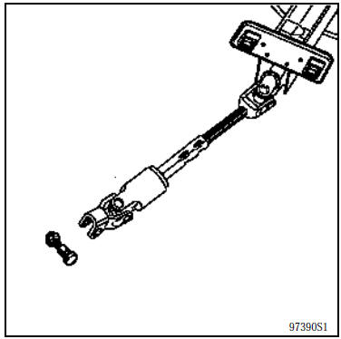
- the nut and cam bolt of the steering clevis after pushing back the boot.
SPECIAL PROCEDURES FOR VEHICLES FITTED WITH DRIVER AIRBAG
CAUTION
To avoid any risk of damaging the clockspring under the steering wheel, observe the following instructions:
- Before disconnecting the steering column from the steering rack, the steering wheel MUST be locked in the straight-ahead position using a "steering wheel lock" tool for the entire duration of the operation.
- Any doubt about the correct centring of the clockspring requires removing the steering wheel in order to apply the centring method described in chapter 88 “Airbag”.
REMINDER: in this case, only trained, qualified personnel may carry out the work
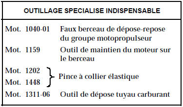
Fit tool Mot. 1159 between the subframe and the cylinder block.
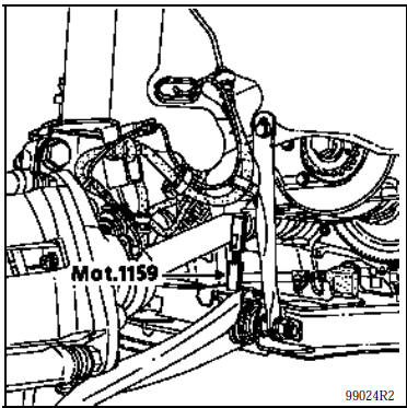
Fit the Mot. 1159 bracket in place of the water pipe mounting on the cylinder block.
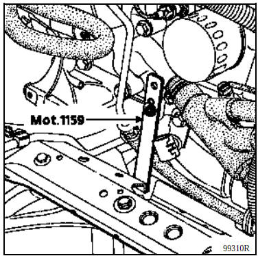
Remove the pendulum mount cover.
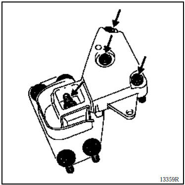
Place a wedge between the gearbox and the subframe.
Remove:
- remove the nut (1), then, using a brass drift, tap to free the stud from the pendulum mount.
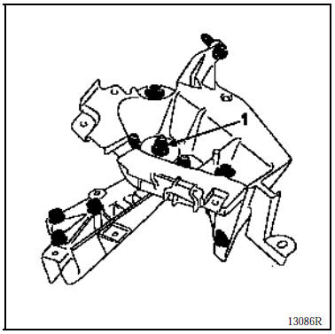
- the mounting bolts (3).
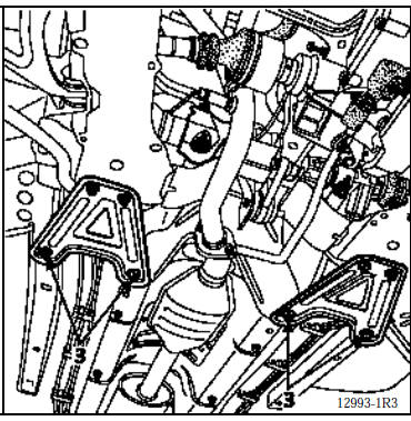
Attach tool Mot. 1040-01 under the subframe.
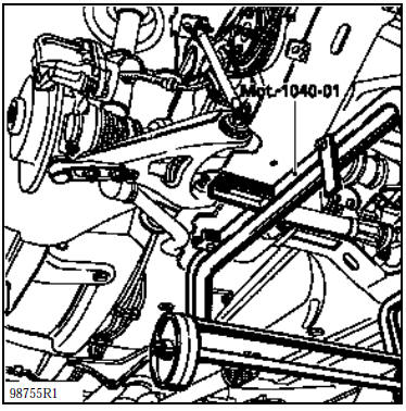
Lower the lift until the tool contacts the ground.
Remove the subframe mounting bolts and lift the powertrain out by raising the body.
NOTE: when an operation requires separating the engine/gearbox/subframe assembly, make sure to mark the position of Mot. 1159 on the subframe.
INSTALLATION
Aligning the subframe with the body will be easier by positioning two Mot. 1233-01 threaded rods in the two front subframe mountings on the body.
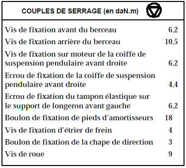
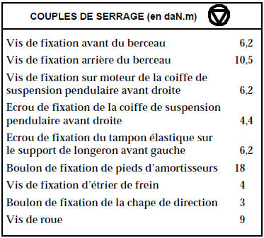
Tighten the subframe mounting bolts to the following torque:
- 6.2 daN.m at the front,
- 10.5 daN.m at the rear.
Refit in the reverse order of removal.
Fit the heat shields correctly.
Fit the caliper mounting bolts with Loctite FRENBLOC and tighten to torque.
Press the brake pedal several times to bring the pistons into contact with the pads.
Carry out:
- top up the engine and gearbox oil if necessary,
- refill and bleed the cooling system (see chapter 19 “Filling and bleeding”).
F8Q engine
REMOVAL
Position the vehicle on a two-post lift.
Remove the battery.
Drain:
- the cooling circuit via the lower radiator hose,
- the gearbox and engine if necessary.
Remove:
- the bonnet,
- the front wheels,
- the cradle-to-body tie rods,
- the mounting bolts (1), spread the brake calipers as shown in the diagram below and secure them to the suspension springs,
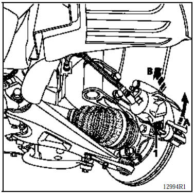
- the shock absorber base bolts,
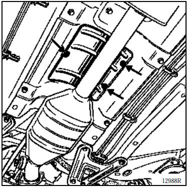
the exhaust heat shield and the gear selector linkage at the lever and gearbox end,
- the exhaust downpipe,
- the earth strap on the gearbox,
- the front bumper,
- the air filter inlet sleeve,
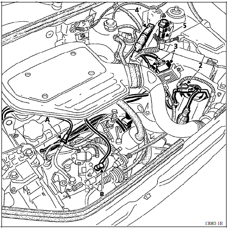
- the fuel supply and return fittings (A) and (B),
- connectors (2), (3), (4) and (5).
Unclip the fuel lines from the air filter housing and the timing cover, and the diesel filter from its bracket, then move the assembly aside.
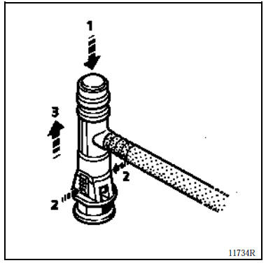
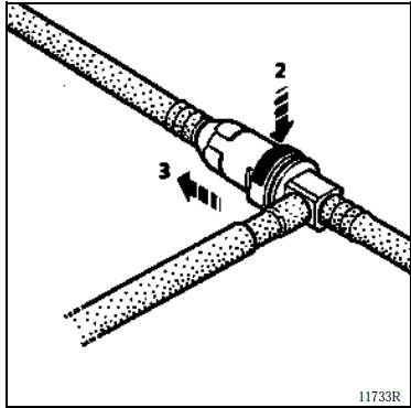
For locking the quick-release fittings, refer to the diagrams below:
Remove the ECU bracket.
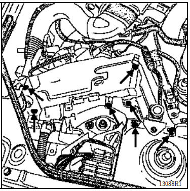
Disconnect:
- the hoses on the expansion tank,
- the brake servo hose,
- the heater hoses (there are two types of connections to disconnect, as shown in the diagrams below),
the relay board (4), the connector (5) and the fuse holder (6) after removing the fuse holders (7),
the accelerator and clutch cables.
Unclip the power steering reservoir and place it on the engine.
Remove:
the upper radiator mountings and tie it to the engine,
the nut and cam bolt of the steering clevis after pushing back the boot.
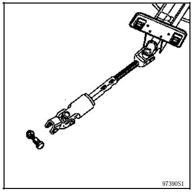
SPECIAL PROCEDURES FOR VEHICLES FITTED WITH DRIVER AIRBAG
CAUTION
To avoid any risk of damaging the clockspring under the steering wheel, observe the following instructions:
Before disconnecting the steering column from the steering rack, the steering wheel MUST be locked in the straight-ahead position using a "steering wheel lock" tool for the entire duration of the operation.
Any doubt about the correct centring of the clockspring requires removing the steering wheel in order to apply the centring method described in chapter 88 “Airbag”.
REMINDER: in this case, only trained qualified personnel may carry out the work.
Fit tool Mot. 1159 between the subframe and the cylinder block.
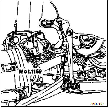
Fit the Mot. 1159 bracket in place of the water pipe mounting on the cylinder block.
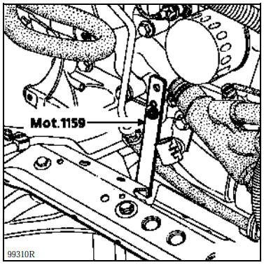
Remove the pendulum mount cover.
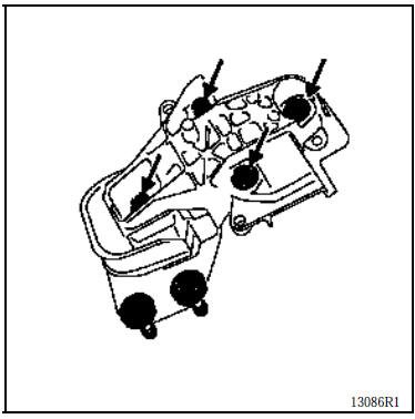
Place a wedge between the gearbox and the subframe.
Remove the nut (1), then, using a brass drift, tap to free the stud from the pendulum mount.
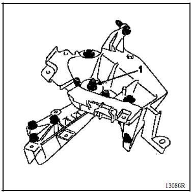
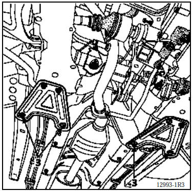
Remove the fixing screws (3).
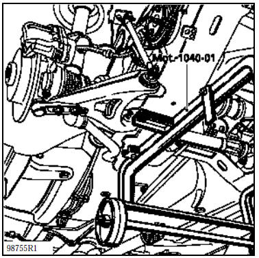
Attach tool Mot. 1040-01 under the subframe.
Lower the lift until the tool contacts the ground.
Remove the subframe mounting bolts and lift the powertrain out by raising the body.
NOTE: when an operation requires separating the engine/gearbox/subframe assembly, make sure to mark the position of Mot. 1159 on the subframe.
INSTALLATION
Aligning the subframe with the body will be easier by positioning two Mot. 1233-01 threaded rods in the two front subframe mountings on the body.
Tighten the subframe mounting bolts to the following torque:
6.2 daN.m at the front,
10.5 daN.m at the rear.
Refit in the reverse order of removal.
Fit the heat shields correctly.
Fit the caliper mounting bolts with Loctite FRENBLOC and tighten to torque.
Press the brake pedal several times to bring the pistons into contact with the pads.
Carry out:
top up the engine and gearbox oil if necessary,
refill and bleed the cooling system (see chapter 19 “Filling and bleeding”).
Test yourself
A quick Renault Kangoo quiz: every answer comes with an explanation and a link to the manual page.