Cylinder head gasket
D7F engine
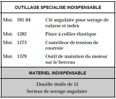
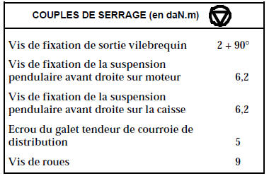
REMOVAL
Place the vehicle on a two-post lift.
Remove the bonnet and the right-hand wheel.
Disconnect the battery.
Drain the cooling system.
Fit engine support tool Mot. 1379.
Remove:
- the timing belt (see the method described in chapter 11 “Timing belt”),
- the oil dipstick,
- the brake servo hose,
- the air filter,
- the accelerator cable,
- the fuel supply and return hoses at the timing belt cover on the cylinder head.
Disconnect:
- the spark plug leads, using tool (3) built into the plastic cover (4),
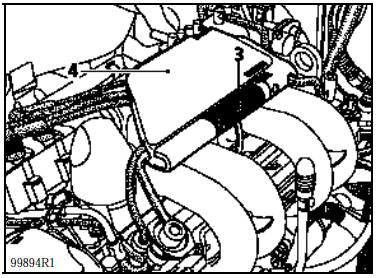
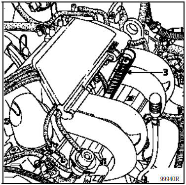
- the canister hose and the fuel vapour recirculation hoses at the solenoid valve,
- the connector of:
- the ignition module,
- the injectors,
- the idle air control stepper motor,
- the throttle position potentiometer,
- the intake air temperature sensor.
Disconnect the water pump–heater hose and the heat shield wiring harness from the rocker cover.
Remove:
- the bolts (5) securing the throttle body stiffening bracket to the cylinder head,
- the nuts (3) securing the manifold to the cylinder head,
- the bolts (4) securing the manifold to the rocker cover,
- the intake manifold, throttle body and injection rail assembly,

- the hoses on the thermostat,
- the rocker cover,
- the cylinder head bolts,
- the cylinder head.
CLEANING
It is very important not to scrape the gasket faces of the aluminium parts.
Use Décapjoint product to dissolve the part of the gasket still stuck.
Apply the product to the area to be cleaned; wait about ten minutes, then remove it using a wooden spatula.
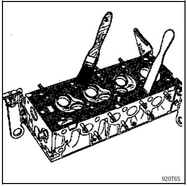
It is recommended to wear gloves during this operation.
We draw your attention to the care required during this operation, to prevent foreign bodies from entering the oil supply passages to the camshaft (passages located both in the cylinder block and in the cylinder head).
Failure to observe this instruction may block the oil jets and cause rapid wear of the camshaft lobes and tappets.
CHECKING THE GASKET FACE
Check for distortion of the gasket face using a straightedge and a set of feeler gauges.
Maximum distortion: 0.05 mm.
No machining of the cylinder head is permitted.
INSTALLATION
The cylinder head is located by two dowels at the rear of the engine.
REMINDER: to obtain correct bolt tightening, use a syringe to remove any oil that may be in the cylinder head bolt holes.
Lubricate the threads and under the bolt heads with engine oil.
Rocker arm adjustment and cylinder head tightening are carried out with the engine cold.
Tighten the cylinder head using the angle-torque gauge (see chapter 07 "Cylinder head tightening").
Tighten using Mot. 591-04.
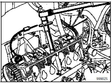
Align the timing belt marks with the marks on the toothed wheels.
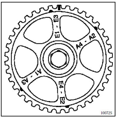
WARNING: the camshaft sprocket has five marks; only the rectangular mark on the face of a tooth indicates Top Dead Centre (TDC); the other marks are used for rocker arm adjustment.
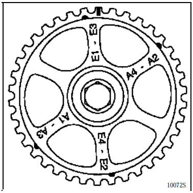
Remove the TDC locating pin.
Refit the timing belt (see method described in chapter 11 "Timing belt").
ROCKER ARM ADJUSTMENT IF NECESSARY
Partially refit the pendulum-support timing cover to the engine using two bolts.
Set the engine to Top Dead Centre, cylinder no. 1 on the firing stroke.
Turn the crankshaft clockwise (viewed from the timing side) until the first mark is reached.
ADJUST: exh 1
exh 3
advance to the second mark:
ADJUST: int 1
int 3
third mark:
ADJUST: exh 2
exh 4
fourth mark:
ADJUST: int 2
int 4
VALVE CLEARANCE VALUES (in mm)
Intake 0.05
Exhaust 0.15
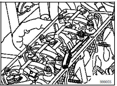
Refit in the reverse order of removal.
Remove the engine support tool from the subframe, Mot. 1379.
NOTE: intake manifold tightening:
- progressively bring the six nuts up to contact with the manifold on the cylinder head, then tighten them to 1.5 daN.m,
- fit the upper bolts and tighten them to 0.9 daN.m.
Fill and bleed the cooling system.
Adjust the accelerator cable.
E7J Engine
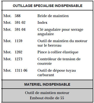
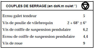
REMOVAL
Position the vehicle on a two-post lift.
Disconnect the battery.
Remove:
- the bonnet,
- the timing belt (see method described in chapter 11, "Timing belt").
Drain the cooling system through the lower hose on the radiator.
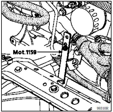
Fit Mot. 1159 between the subframe and the cylinder block.
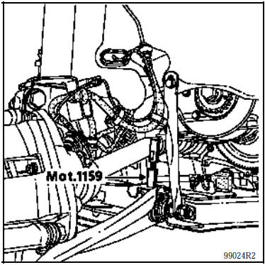
Fit the Mot. 1159 bracket in place of the water pipe mounting on the cylinder block, then remove the engine support tool.
Remove:
- the connector and the hose on the absolute pressure sensor,
- the stepper motor connector,
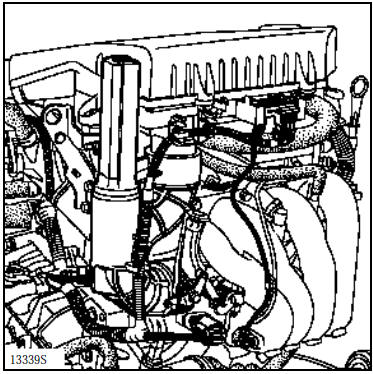
- the decorative cover on the air filter assembly,
- the air filter assembly,
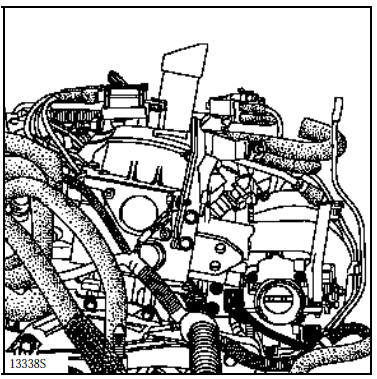
- the throttle position potentiometer connector,
- the accelerator cable,
- the air inlet duct, disconnecting the intake air temperature sensor connector,
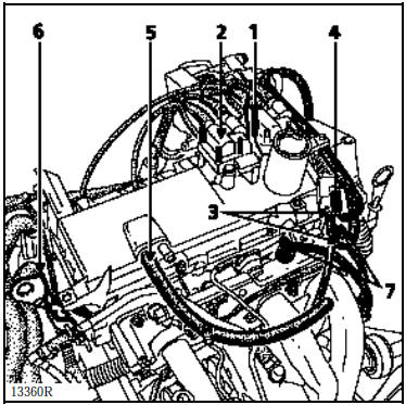
the ignition coil connectors and connector (1),
the coil (2),
the hoses (3) and the connector (4),
the hose (5),
the lifting lug (6),
the fuel supply and return hoses (7) using Mot. 1311-06,
the injector connectors,
the cylinder head cover,
the wiring connector and the hoses on the thermostat housing,
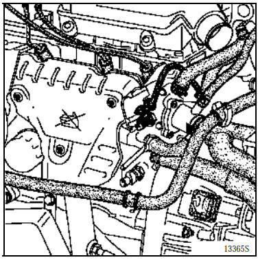
the heat shield and the exhaust downpipe,
the alternator,
the bracket (8) and the connector (9) of the pressure switch,
the power steering pump mounting bolt and move the pump aside,
the multi-function bracket mounting bolts and move the bracket aside,
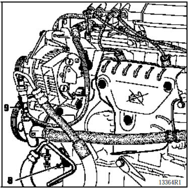
the bracket (10),
the support bracket bolt (11) and loosen the nut (12),
the oil dipstick tube mounting bolt (13),
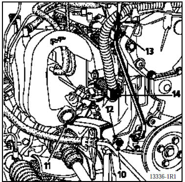
Unclip the wiring harness at (14).
Remove:
the cylinder head bolts except bolt (F), which should only be loosened, then pivot the cylinder head around bolt (F),
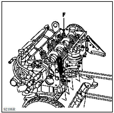
the cylinder head.
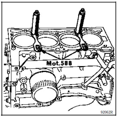
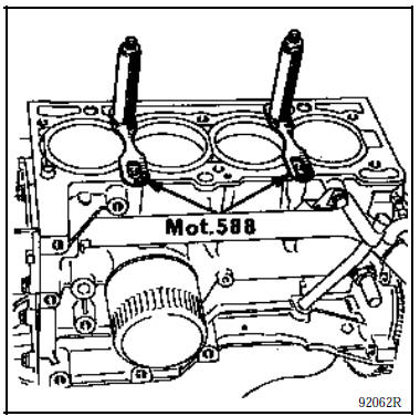
Fit the cylinder liner retaining clamps Mot. 588.
CLEANING
It is very important not to scrape the gasket surfaces of aluminium parts. Use Décapjoint to dissolve the part of the gasket still stuck.
Apply the product to the area to be cleaned; wait about ten minutes, then remove it using a wooden spatula.
It is recommended to wear gloves during this operation.
Take care when carrying out this operation to prevent foreign matter from entering the pressurised oil supply passages to the rocker gallery (passages located in both the cylinder block and the cylinder head).
Failure to observe this instruction may block the rocker jets and rapidly damage the camshaft lobes and rocker pads.
Check for distortion of the gasket face using a straightedge and a set of feeler gauges.
Maximum distortion 0.05 mm.
No machining of the cylinder head is permitted.
REFITTING (Specific points)
Remove the cylinder liner clamps Mot. 588.
Check that the locating dowel (A) is in place.
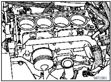
Position the cylinder head gasket.
Lubricate the threads and under-head bearing surfaces of the bolts with engine oil.
Refit the cylinder head (shortest bolts on the intake side).
Tighten the cylinder head (see section 07 “Cylinder head tightening”).
Refit the timing belt (see section 11 “Timing belt”).
Correctly refit the heat shields.
Refit in reverse order of removal.
Fill and bleed the cooling system (see section 19 “Filling and bleeding”).
ROCKER ARM ADJUSTMENT IF NECESSARY
Valve clearance settings (cold) (in mm):
intake 0.10
exhaust 0.25
“Seesaw” method
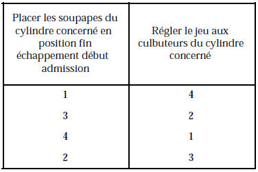
Exhaust valve fully open method
Bring the exhaust valve of cylinder no. 1 to fully open and adjust the intake valve clearance of cylinder no. 3 and the exhaust valve clearance of cylinder no. 4.
Repeat for the other cylinders, following the order given in the table.
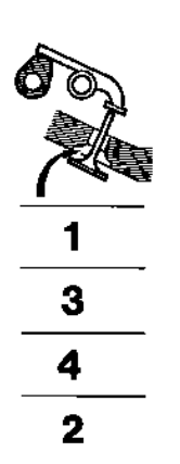
Exhaust valve to be fully open.
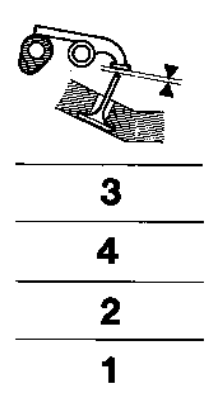
Intake valve to be adjusted.
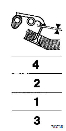
Exhaust valve to be adjusted.
F8Q engine
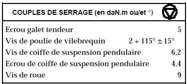
REMOVAL
Position the vehicle on a two-post lift.
Disconnect the battery.
Remove:
the bonnet,
the timing belt (see method described in section 11 “Timing belt”).
Drain the cooling system through the lower hose on the radiator.
Fit tool Mot. 1159 between the subframe and the cylinder block.
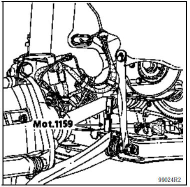
Fit the Mot. 1159 bracket in place of the water pipe mounting on the cylinder block, then remove the engine support tool.
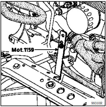
Remove:
the exhaust downpipe,
the hoses and the connector of the cylinder head coolant outlet housing,
the union (1) using Mot. 1311-06,
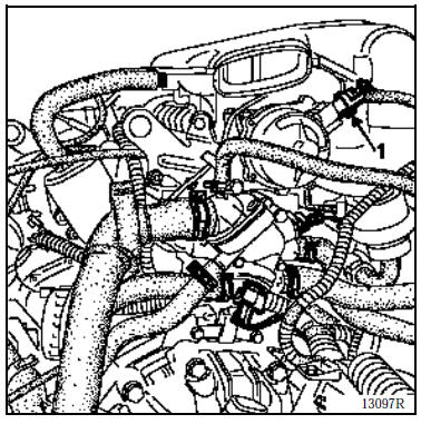
the air filter assembly, disconnecting the EGR solenoid valve and air temperature sensor connectors (unclip the fuel hoses from the air filter housing),
the air intake duct,
the accelerator cable,
the glow plug supply wires,
the instrumented injector connectors and the fast idle solenoid valve connector (5),
the fuel supply and return unions at (A) and (B).
Disconnect the connector (6) from the diesel filter, unclip it from its bracket and move the fuel hose and diesel filter assembly aside.
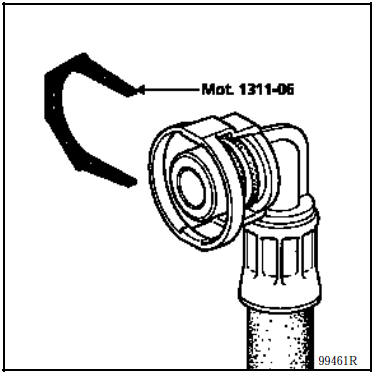
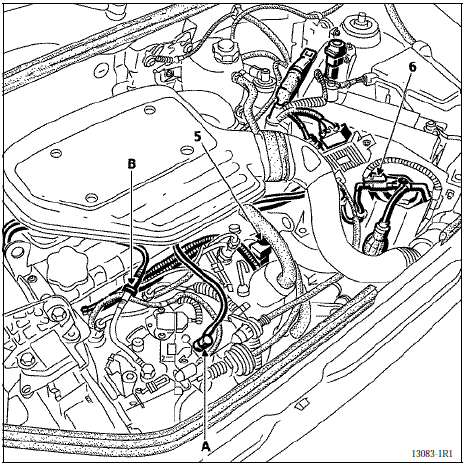
To release the quick-connect fittings, refer to the diagrams below.
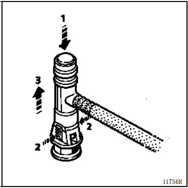
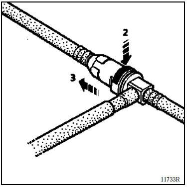
Remove the fuel hose bracket (7).
Loosen, without removing, the lower timing cover mounting bolts.
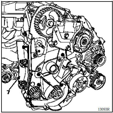
Remove:
the auxiliary belt tensioner system,
the cylinder head bolts.
Free the cylinder head by levering the lower part of the lower camshaft cover away; do not pivot the cylinder head, as it is located by two dowels (C).
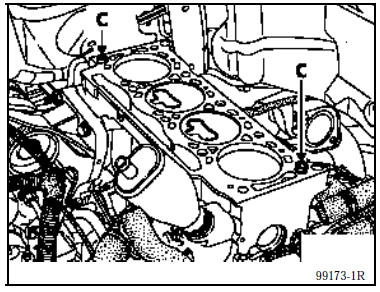
Use a syringe to remove any oil that may be in the cylinder head bolt holes.
This is necessary to achieve correct bolt tightening.
Protect the oil feed passage to prevent foreign matter from entering the oil supply passages in the cylinder head.
Failure to observe this instruction may block the oil supply passages and rapidly damage the camshaft.
CLEANING
It is important not to scrape the gasket surfaces of aluminium parts. Use Décapjoint to dissolve the part of the gasket still stuck.
Apply the product to the area to be cleaned; wait about ten minutes, then remove it using a wooden spatula.
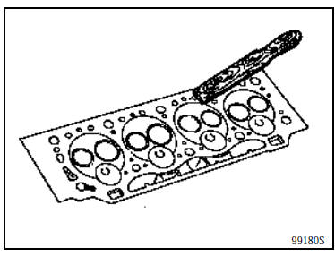
It is recommended to wear gloves during this operation.
CHECKING THE GASKET FACE
Check for distortion of the gasket face using a straightedge and a set of feeler gauges.
Maximum distortion 0.05 mm.
No machining of the cylinder head is permitted.
Pressure test the cylinder head to check for any cracks.
Engine F8Q 11-
CHECKING CYLINDER HEAD GASKET THICKNESS
Checking piston protrusion
Clean the piston crowns to remove carbon deposits.
Turn the crankshaft one revolution in the direction of rotation to bring piston no. 1 close to TDC.
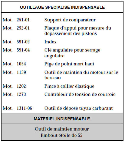
Place tool Mot. 252-01 on the piston.
Fit tool Mot. 251-01 fitted with a dial gauge onto support plate Mot. 252-01, with the gauge plunger resting on the cylinder block, and find the piston TDC.
NOTE: all measurements must be taken along the longitudinal axis of the engine to eliminate errors caused by piston rocking.
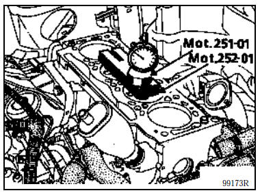
Measure the piston protrusion.
ONLY CONSIDER THE PISTON WITH THE MAXIMUM PROTRUSION.
For a maximum engine piston protrusion of:
less than 0.868 mm, use a gasket marked by a tab with two holes,
between 0.868 mm and 1 mm, use a gasket marked by a tab with one hole,
greater than 1 mm, use a gasket marked by a tab with three holes.
REFITTING (Specific points)
Refit the previously selected cylinder head gasket.
It is located by two dowels (C).
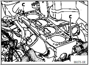
Position the pistons at mid-stroke to avoid any contact with the valves when tightening the cylinder head.
Locate the cylinder head on the dowels.
Lubricate under the heads and on the thread of the fastening bolts.
Cylinder head tightening (see chapter 07 'Cylinder head tightening').
Refit in the reverse order of removal.
Refit the timing belt (see method described in chapter 11 'Timing belt').
Fill and bleed the cooling system (see chapter 19 'Filling/bleeding').
Test yourself
A quick Renault Kangoo quiz: every answer comes with an explanation and a link to the manual page.