Chassis
Subframe
In this manual: Chassis
~3min read
Essential equipment |
| steering wheel lock |
| unit support jack |
| diagnostic tool |
Tightening torques |
|
| rear crossmember to subframe bolts | 6.2 daN.m |
| lower balljoint bolts | 6.2 daN.m |
| subframe brace bolts | 10.5 daN.m |
| torque reaction link to engine bolts (F engines) | 18 daN.m |
| torque reaction link to engine bolts (K engines) | 10.5 |
| torque reaction link to subframe bolts | 10.5 daN.m |
| anti-roll bar link nuts | 4.4 daN.m |
| steering tie rod end nuts | 3.7 daN.m |
| front radiator crossmember mountings | 10.5 daN.m |
| side member brace bolts | 2.1 daN.m |
| folding yoke bolt | 2.4 daN.m |
| wheel bolt | 11 daN.m |
| battery cover screw | 0.4 daN.m |

Never use the lower arm as a support point for the lifting equipment.
REMOVAL
- Position the vehicle on a two-post lift.
- Set the wheels straight.
- Center the steering wheel.
- Place the folding yoke bolt and nut in the passenger compartment.
- Fit the steering wheel lock tool.
- Disconnect the battery, starting with the negative terminal.
- Strap the radiator to the grille.
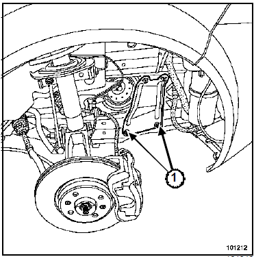
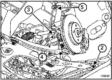
- Remove:
- the front wheels,
- the mudguards,
- the engine undershield,
- the lower bolts (1) of the side reinforcements,
- the front radiator crossmember mounting bolts (2),
- the rear radiator crossmember mounting nuts,
- the radiator crossmember.
- Unclip the wheel speed sensor wiring.
- Disconnect the wheel speed sensor connector in the wheel arch.
- Remove:
- the steering tie-rod ball joint nuts (3),
- the lower ball joint bolts (4),
- the upper ball joint nuts (5) of the anti-roll bar drop links.
- Separate the ball joints.
K4J or K4M or K9K
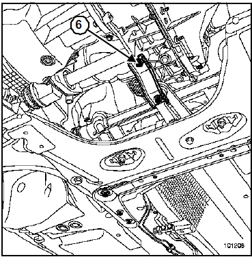
- Remove the torque strut bolt (6) on the engine.
F4R or F9Q
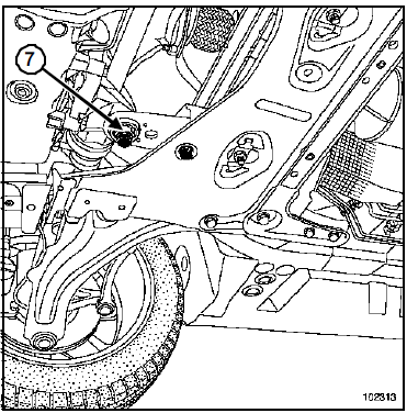
- Remove the torque strut bolt (7) on the engine.
- Position the powertrain jack tool under the subframe.
- Strap the subframe to the powertrain jack tool.
- Separate the ball joints from the lower arms.
- Remove the wheel speed sensor wiring bracket.
- Remove:
- the rear crossmember mounting bolts,
- the subframe mounting bolts to the body,
- the rear crossmember,
- the subframe.
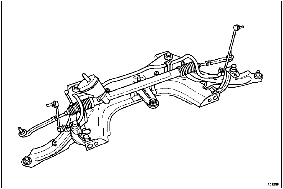
- Remove the components from the subframe.
INSTALLATION
WARNING- Always replace the subframe and arm mounting bolts.
- Always fit a 10 mm thick shim between the radiator crossmember and the subframe.
Set the wheels straight; center the steering wheel.
- Refit in the reverse order of removal.
- Tighten to the following torques:
- the rear crossmember bolts on the subframe (6.2 daN.m),
- the lower ball joint bolts (6.2 daN.m),
- the subframe tie rod bolts (10.5 daN.m),
- the torque strut bolts on the engine (F engines) (18 daN.m),
- the torque strut bolts on the engine (K engines) (10.5),
- the torque strut bolts on the subframe (10.5 daN.m),
- the anti-roll bar drop link ball joint nuts (4.4 daN.m),
- the steering tie-rod ball joint nuts (3.7 daN.m),
- the front radiator crossmember mounts (10.5 daN.m),
- the side reinforcement bolts (2.1 daN.m),
- the folding yoke bolts (2.4 daN.m),
- the wheel fixing bolts (11 daN.m).
Connect the battery; carry out the necessary learning procedures (Chapter Battery).
Adjust the running gear (see General chapter).
Carry out the torque and angle sensor learning procedure using the diagnostic tool (Chapter Power Steering).
Note: Be sure to initialise the xenon lighting system (if the vehicle is so equipped; see Xenon lamps chapter).- Battery cover bolts (0.4 daN.m).
Test yourself
A quick Renault Megane quiz: every answer comes with an explanation and a link to the manual page.
Was this page helpful?