Interpreting states
| ET012 | PRIMARY BRAKE SWITCH |
INSTRUCTIONS
Particular points: Carry out the checks only if the "INACTIVE" and "ACTIVE" states are inconsistent with the pedal position.
"INACTIVE" state: brake pedal pressed.
If the stop lights work:- Check and ensure continuity of the link between pin 1 of the brake light switch connector and pin 30 of the ECU connector.
If the stop lights do not work:
- Check the condition and installation of the brake switch as well as the brake light fuse.
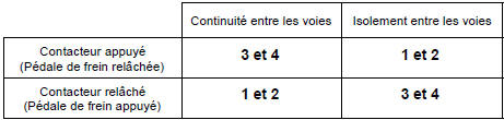
- Remove and test the operation of the brake switch:
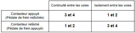
- Replace the brake switch if necessary.
- Check / confirm the presence of +APC on pins 2 and 4 of the brake switch connector.
"ACTIVE" state: brake pedal released.
|
|
AFTER REPAIR
Carry out a road test followed by a check with the diagnostic tool.
| ET040 | CLUTCH PEDAL |
INSTRUCTIONS
Particular points: Carry out the checks only if the "INACTIVE" and "ACTIVE" states are inconsistent with the pedal position.
"INACTIVE" state: clutch pedal pressed.
- Check the condition and installation of the clutch switch.
- Check and ensure continuity of the link between pin 1 of the clutch switch connector and pin C4 of the 32-way black ECU connector.
- Check and ensure ground is present on pin 2 of the clutch switch connector.
Repair if necessary.
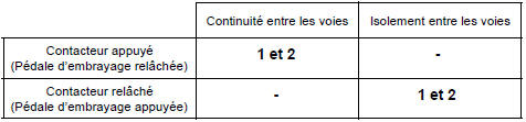
- Remove and test the operation of the clutch switch:
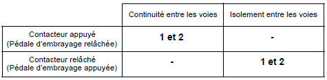
- Replace the brake switch if necessary.
"ACTIVE" state: clutch pedal released.
|
|
AFTER REPAIR
Carry out a road test followed by a check with the diagnostic tool.
| ET042 | CRUISE CONTROL / SPEED LIMITER |
INSTRUCTIONS
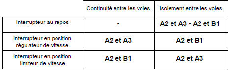
Particular points: Carry out the checks only if the states are inconsistent with the button positions.
STATE 1 and STATE 2 absent, on/off switch pressed (ET042 "INACTIVE").
Check the connections of the cruise control on/off switch and the ECU (32-way black connector). Repair if necessary.
|
|
|
AFTER REPAIR
Carry out a road test followed by a check with the diagnostic tool.
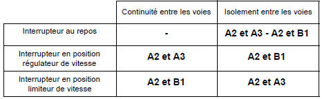
STATE 1, STATE 2, switch at rest.
| Check the connections of the cruise control on/off switch and the ECU (32-way black connector). Repair if necessary. |
|
|
AFTER REPAIR
Carry out a road test followed by a check with the diagnostic tool.
INSTRUCTIONS
Particular points: Carry out the checks only if the states are inconsistent with the button positions.
STATE 3, STATE 4, STATE 5 and STATE 6 absent, button pressed (ET042 "INACTIVE").
 If the values are not within specification, replace the steering wheel controls. |
Reconnect the 3-way black connector and carry out the same measurements from the 32-way black ECU connector between pins D3 and D2.
Carry out the necessary repairs.
|
AFTER REPAIR
Carry out a road test followed by a check with the diagnostic tool.
INSTRUCTIONS
Particular points: Carry out the checks only if the states are inconsistent with the button positions.
STATE 3, STATE 4, STATE 5, STATE 6, button released.
 If the values are not as specified, replace the steering wheel controls. |
Reconnect the 3-way black connector and carry out the same measurements from the 32-way black ECU connector between pins D3 and D2.
Carry out the necessary repairs.
|
AFTER REPAIR
Carry out a road test followed by a check with the diagnostic tool.
Test yourself
A quick Renault Megane quiz: every answer comes with an explanation and a link to the manual page.