Chassis
Steering column adjustment handle: Replacement
In this manual: Chassis
~5min read
Essential equipment |
| diagnostic tool |
Tightening torques |
|
| electric column lock mounting bolt | 0.8 daN.m |
| steering column mounting nuts | 2.1 daN.m |
| folding yoke bolt | 2.4 daN.m |
| shell bolts | 0.2 daN.m |
| steering wheel bolt | 4.4 daN.m |
| battery cover screw | 0.4 daN.m |

- Before any work on the airbag system, lock the electronic control unit using the diagnostic tools (Chapter Electrical equipment).
- Never handle pyrotechnic systems (airbags and pretensioners) near a heat source or flame; there is a risk of deployment.
These operations do not require a vehicle lift.
Note: Locking the electronic control unit also unlocks the electric column lock.REMOVAL
- Disconnect the battery, starting with the negative terminal.
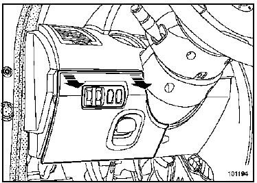
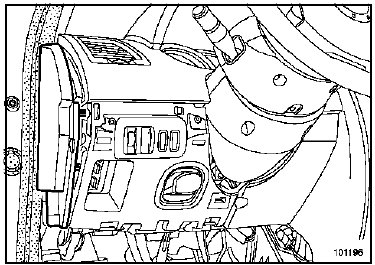
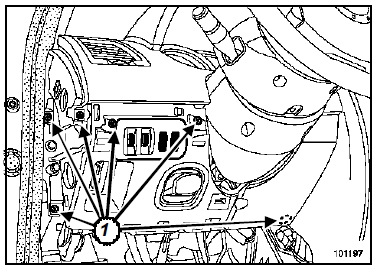
- Unclip:
- the access hatch to the lower housing,
- the side trim,
- the headlamp levelling control.
- Remove the screws (1).
- Disconnect the connectors from the headlamp levelling control.
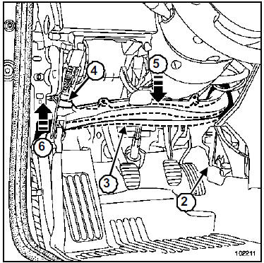
- Unclip the air duct (3) at (4).
- Bend the air duct (3) downwards at (5).
- Lift the air duct at (6).
- Remove the air distribution duct (3).
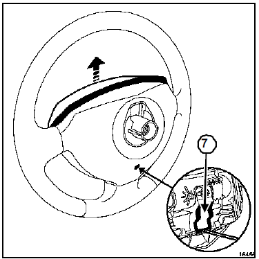
- Insert a screwdriver through the hole at the rear of the steering wheel.
- Unlock the system (7).
- Remove the driver's frontal airbag.
- Disconnect the airbag connector.
- Set the wheels straight.
- Disconnect the connectors in the steering wheel.
- Remove:
- the steering wheel bolt,
- the steering wheel.
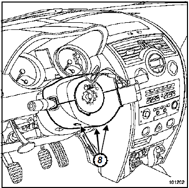
- Remove:
- the three lower screws (8),
- the upper and lower shrouds.
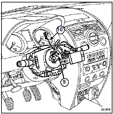
- Mark the position of the under-steering-wheel control assembly.
- Check that the "0" mark on the clockspring (9) is correctly aligned with the index.
- Remove the under-steering-wheel control assembly.
- Loosen the screw (10).
- Unclip the complete steering column assembly.
- Disconnect:
- the various connectors (wiper, radio control and lighting),
- the clockspring connector
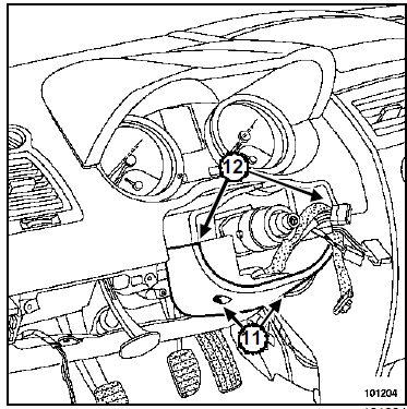
- Remove the two screws (11).
- Unclip the two upper clips (12).
- Partially remove the second lower shroud.
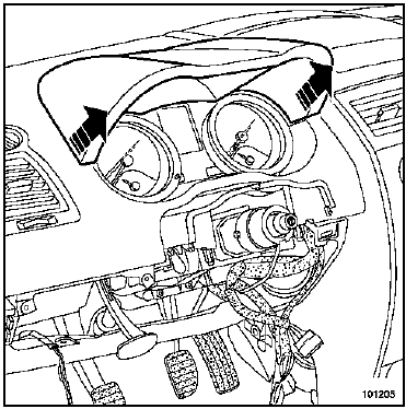
- Remove the dashboard visor.
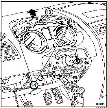
- Remove the upper screw (13).
- Press on the two clips (14).
- Remove the dashboard.
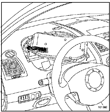
- Disconnect the dashboard connector.
- Partially remove the driver's side carpet.
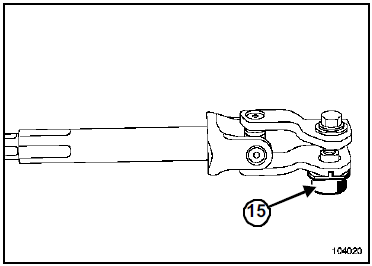
- Eject the bell (15) (do not reuse it).
- Remove the folding clamp screw.
- Disconnect:
- the steering column lock connector,
- the power connector of the electric power steering computer using a screwdriver 4 mm wide and 0.5 mm thick.
- the signal connector of the electric power steering computer using a screwdriver 4 mm wide and 0.5 mm thick.
- Unclip the clockspring harness from the steering column.
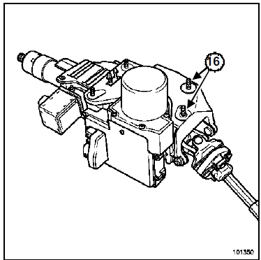
- Access the mounting nuts (16) from the rear of the steering column, between the steering column intermediate shaft and the brake pedal.
- Remove the nuts.
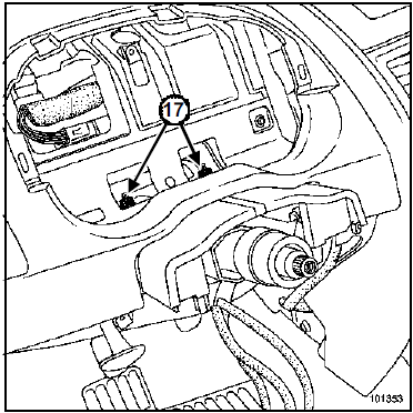
- Remove the two steering column mounting nuts (17).
Right-hand drive specific
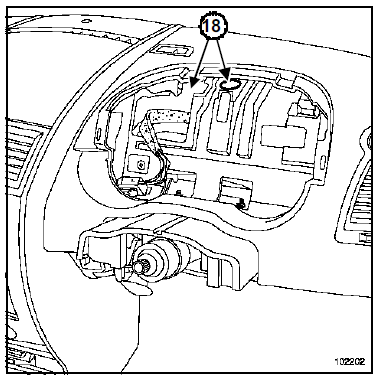
- Access the front steering column mounting nuts through the holes in the dashboard (18).
- Unclip the centring ring.
- Remove the steering column.
- When replacing the steering column, remove the column lock.
- The column lock is secured by a screw with a left-hand thread.
- Remove the adjustment handle.
- Remove the two front steering column mounting nuts.
- Unclip the centring ring.
- Remove the steering column.
INSTALLATION
- Tighten the electric lock fixing screw to torque (0.8 daN.m).
- Refit in the reverse order of removal.
- When replacing the electric lock (see Electrical Equipment chapter).
- If the centring ring is damaged when removing the steering column, remove the centring ring. Do not replace it when refitting the steering column.
- On a new steering column, the cam nut of the folding clamp is pre-fitted.
Push and pull on the power and signal connectors of the electric power steering computer to check that the connectors are correctly locked (risk of loss of power assistance).
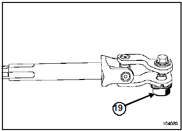
- Observe the fitting direction of the screw and the folding clamp cam nut.
- The screw, the folding clamp cam nut and the steering wheel screw must be replaced.
- Do not refit the bell (19) if the steering column is not being replaced.
- Refit the folding clamp.
- Refit the cam nut and the clamp screw.
- Bring the cam nut and the clamp screw together.
- Secure the cam nut in its housing (in the folding clamp).
- Refit in the reverse order of removal.
- Tighten to torque:
- the steering column mounting nuts (2.1 daN.m),
- the folding clamp screw (2.4 daN.m),
- the shroud screw (0.2 daN.m),
- the steering wheel screw (4.4 daN.m).
- Set the steering column to the locked upper position.
- Refit the lower part of the dashboard and the shrouds.
- Reconnect the battery.
- Carry out the necessary relearning procedures (see Battery chapter).
- Carry out the torque and angle sensor relearning and the necessary configurations using the diagnostic tool (see diagnostic manual).
- Perform a complete check using the diagnostic tool.
- Clear the fault generated using the diagnostic tool.
- Torque the battery cover screws (0.4 daN.m).
Test yourself
A quick Renault Megane quiz: every answer comes with an explanation and a link to the manual page.
Was this page helpful?