Preliminaries
1. APPLICABILITY OF THIS DOCUMENT
This document describes the diagnosis applicable to all Electronic Control Units with the following characteristics:
| Vehicle(s): MEGANE II Function concerned: AUTOMATIC GEARBOX |
Control unit name: Siemens TA 2000 Program no.: 94 VDIAG no.: 10 |
2. ESSENTIAL ITEMS FOR DIAGNOSIS
Documentation type:
Diagnostic methods (this document):
- Assisted diagnosis (built into the diagnostic tool), paper (Repair Manual or Technical Note), Dialogys.
Wiring diagrams:
- Visu-Schéma (CD-ROM), paper.
Diagnostic tool type:
- CLIP
Essential tool type:
Essential special tools |
|
| Multimeter | |
| Elé. 1681 | Universal breakout box |
| Elé. 1588 | Terminal block |
3. REMINDERS
Procedure
To diagnose the vehicle control units, switch the ignition to diagnostic mode (+ after forced ignition).
Proceed as follows:
- Vehicle card on card holder (vehicles without key, scenario 1, entry level, without hands-free) and scenario 2 (high end, hands-free).
- Long press (more than 5 seconds) on the "start" button outside starting conditions.
- Then connect the diagnostic tool and carry out the required operations.
The left and right Xenon headlamp control units are powered when the dipped beam headlamps are switched on.
Their diagnosis is therefore only possible after switching the ignition on in diagnostic mode (or after forced ignition) and switching on the dipped headlights.
To cut the + after ignition (+AC), proceed as follows:
- Disconnect the diagnostic tool.
- Make two short presses (less than 3 seconds each) on the "start" button.
- Check that the +after ignition forced is switched off by the computer warning lights on the instrument panel going out.
Faults
There are declared present faults and declared stored faults (which appeared under certain conditions and have since cleared, or are still present but were not diagnosed under the current conditions).
The "present" or "stored" state of the faults must be considered when the diagnostic tool is used after switching on + After ignition (without any action on the system components).
For a present fault, follow the procedure given in the chapter "Fault interpretation".
For a stored fault, record the displayed faults and follow the instructions in the "Instructions" section.
If the fault is confirmed when the instruction is applied, the fault is present. In this case, repair the fault.
If the fault is not confirmed, check:
- the electrical circuits corresponding to the fault,
- the connectors of these circuits (corrosion, bent pins, etc.),
- the resistance of the component detected as faulty,
- the condition of the wiring (melted or cut insulation, chafing).
Conformity check
The conformity check aims to verify the states and parameters that show no fault on the diagnostic tool when they are inconsistent. This step therefore allows you to:
- To diagnose faults with no fault displayed that may correspond to a customer complaint.
- To check correct system operation and make sure a fault will not reappear after the repair.
This chapter therefore contains a diagnosis of states and parameters, under the conditions required for their check.
If a state does not operate normally or a parameter is out of tolerance, refer to the corresponding diagnostic page.
Customer symptoms - Fault location tree
If the diagnostic tool check is correct but the customer complaint is still present, treat the problem as a "customer symptom".
A summary of the overall procedure is available as a flowchart on the following page4. DIAGNOSTIC PROCEDURE
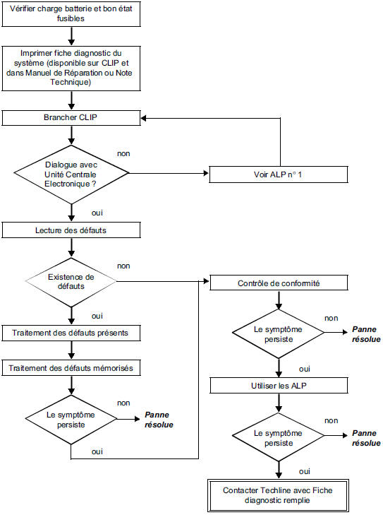
5. DIAGNOSTIC SHEET
WARNINGAll incidents on a complex system must be subject to a full diagnosis using suitable tools. The DIAGNOSTIC SHEET, to be completed during diagnosis, provides and keeps a record of the diagnosis carried out. It is an essential element of communication with the manufacturer.
A DIAGNOSTIC SHEET MUST THEREFORE BE COMPLETED EACH TIME A DIAGNOSIS IS CARRIED OUTThis sheet will always be requested:
- When requesting technical assistance from the techline.
- For approval requests, when replacing parts that require mandatory approval.
- To be attached to the "monitored" parts returned. It is then required for warranty reimbursement and helps with a better analysis of the removed parts.
6. SAFETY INSTRUCTIONS
Any operation on a component requires safety rules to avoid any material damage or personal injury:
- Check that the battery is correctly charged to avoid damage to the ECUs in case of low charge.
- Use the appropriate tools.
7. ABBREVIATIONS GLOSSARY
ABS: Anti-lock braking system
ALP: Fault locating tree
APC: After ignition (after contact)
BVA: Automatic gearbox
CAN: Controller area network
CC: Short circuit
CO: Open circuit
D: Drive
P/N: Park/Neutral position
R: Reverse
Test yourself
A quick Renault Megane quiz: every answer comes with an explanation and a link to the manual page.