Interpreting states
| ET001 | SOLENOID VALVE POWER SUPPLY |
INSTRUCTIONS
No fault must be present or stored.
| Force the solenoid valve power supply by running test AC024 "Sequential actuator control" described in the "Control mode processing" section. Disconnect the ECU. Check the cleanliness and condition of the connector. |
| Use the "Universal breakout box Elé. 1681". Check the insulation, continuity and absence of parasitic resistance of the solenoid valve circuits. (See the "System operation and pin assignment" chapter for the location of the "modular connector" connections.) With power on:
|
| Reconnect the "modular connector" and check that the control current of a solenoid valve is 250 mA when the solenoid valve is "ACTIVE". |
| If the state does not operate correctly, follow the procedure for fault DF012 "Solenoid valve power supply". |
| If the fault persists, contact your Techline. |
AFTER REPAIR
Restart the conformity check from the beginning.
| ET003 | BRAKE SWITCH (OPENING) |
INSTRUCTIONS
No fault must be present or stored.
| Check that the state is "ACTIVE" with the pedal released, and changes to "INACTIVE" when the brake pedal is pressed. |
| Check the cleanliness and condition of the brake switch connector. |
| Check the position, adjustment and correct operation of the brake switch. |
| Disconnect the battery. Disconnect the ECU. Check the cleanliness and condition of the connector. Use the "Universal breakout box Elé. 1681". Check the insulation, continuity and absence of parasitic resistance of the following links:ECU pin 16 → Pin 3 brake switch Repair if necessary. If the state does not operate as indicated, replace the sensor. |
AFTER REPAIR
Restart the conformity check from the beginning.
| ET010 | OIL TOO HOT INFORMATION |
INSTRUCTIONS
No fault must be present or stored
| This state indicates a transmission oil temperature above normal operating temperature. The state is "NO" if the transmission oil temperature is below 140 °C. The state changes to "YES" when the transmission oil temperature rises above 140 °C. |
| Once the state has changed to "YES", the transmission oil temperature must drop below 130 °C for the state to change back to "NO". |
| If the state does not operate as indicated: apply the interpretation of fault DF177 "Automatic transmission overheating". |
| If the fault persists, contact your Techline. |
AFTER REPAIR
Restart the conformity check from the beginning.
| ET012 | GEAR SELECTOR POSITION |
INSTRUCTIONS
No fault must be present or stored.
SELECTOR LEVER POSITION "P"-"R"-"N"-"D"
| Check the cleanliness, condition and mounting of the automatic transmission multifunction switch. Check the adjustment of the control. To do so, refer to the repair manual. |
| Disconnect the battery. Disconnect the "modular connector" and check the cleanliness and condition of connector "A" connections. (See the "System operation and pin assignment" chapter for the location of the "modular connector" connections.) |
| Carry out the following checks on the multifunction switch: Continuity: Lever in position "P", pin A10 → pin A7 Insulation: Lever in position "P", pin A9, A11, A12 → pin A7 |
| Disconnect the multifunction switch. Connect the "Universal breakout box Elé. 1681" in place of the ECU and check the insulation, continuity and absence of parasitic resistance of the connections between: ECU pin 31 → Pin A10 multifunction switch Repair if necessary. |
AFTER REPAIR
Restart the conformity check from the beginning.
INSTRUCTIONS
No fault must be present or stored.
SELECTOR LEVER POSITION "M" Increment "M+" AND "M-"
| Check the cleanliness and condition of the pulse switch module connector. |
| Disconnect the battery. Disconnect the ECU. Check the cleanliness and condition of the connectors. Use the "Universal breakout box Elé. 1681". Check the insulation, continuity and absence of parasitic resistance of the following links:ECU pin 36 → Pin B3 Pulse switch module Repair if necessary. |
| If the fault is still present, replace the pulse switch module. |
AFTER REPAIR
Restart the conformity check from the beginning.
| ET013 | ENGAGED GEAR |
INSTRUCTIONS
No fault must be present or stored.
|
| If the problem comes from the torque converter lock-up, apply the interpretation of faults DF016 "Lock-up solenoid valve circuit", DF018 "Lock-up slip" and DF120 "Controlled slip". |
| If the problem comes from the engaged gear, carry out a diagnosis of the multifunction switch. Check that states ET123, ET124, ET125 and ET126 operate correctly. Check the adjustment of the multifunction switch. |
| If the fault persists, contact your Techline. |
AFTER REPAIR
Restart the conformity check from the beginning.
| ET020 | SOLENOID VALVE CONTROL – CONVERTER FLOW CONTROL |
INSTRUCTIONS
No fault must be present or stored.
| The converter flow control solenoid valve is "ACTIVE" if the transmission oil temperature is above 100 °C and the engine speed is above 2000 rpm. In all other cases, the solenoid valve remains inactive. |
| Run test AC024 "Sequential actuator control" and check that the control state changes from "INACTIVE" to "ACTIVE". Powered on, the "ACTIVE" solenoid valve must read 0 V. Powered on, the "INACTIVE" solenoid valve must read 12 V. |
| Reconnect the control module. Activate the solenoid valves using command AC024 "Sequential actuator control" and check the solenoid valve current. If the current is 260 mA, the solenoid valve is operating correctly. If the current is lower, check the connectors and the wiring from the control module to the flow exchanger solenoid valve. |
| If the command does not change state, apply the diagnostic procedure for DTC DF017 "Flow exchanger solenoid valve circuit". |
| After completing the diagnostic procedure for DTC DF017 "Flow exchanger solenoid valve circuit", if the fault persists, contact your Techline. |
AFTER REPAIR
Restart the conformity check from the beginning.
| ET021 | SEQUENCE 1 SOLENOID VALVE CONTROL |
INSTRUCTIONS
No fault must be present or stored
| This status shows the solenoid valve state: "ACTIVE / INACTIVE". This status must be "INACTIVE" for all selector lever positions. |
| Disconnect the ECU. Check the cleanliness and condition of the connector. Check the continuity between pin 9 of the control module connector and pin B8 of the "modular connector". Check between pins 1 and 9 of the control module connector that the resistance of sequence solenoid valve no. 1 is 40 Ω ±2 Ω at approximately 20 °C. |
| If the resistance is greater than 50 Ω, check the wiring, the control module connector and the "modular connector". |
| Reconnect the control module. Activate the solenoid valves using command AC024 "Sequential actuator control" and measure the solenoid valve current. If the current is 250 mA, the solenoid valve is operating correctly. If the current is lower, check the connectors and the wiring from the control module to the solenoid valve. |
| If the status does not operate as shown: apply the diagnostic procedure for DTC DF085 "Sequence solenoid valve E.V.S.1 circuit". |
| If the problem is still not resolved, replace the electro-hydraulic interface. |
AFTER REPAIR
Restart the conformity check from the beginning.
Check that all gears upshift and downshift correctly.
| ET022 | SEQUENCE 2 SOLENOID VALVE CONTROL |
INSTRUCTIONS
No fault must be present or stored.
| This status shows the solenoid valve state. This status must be "INACTIVE" when the selector lever is in positions: "P", "R", "N", "D". This status must be "ACTIVE" when the selector lever is in positions: "M", "M+", "M-". |
| Disconnect the ECU. Check the cleanliness and condition of the connector. Check the continuity between pin 9 of the control module connector and pin B8 of the "modular connector". Check between pins 1 and 9 of the control module connector that the resistance of sequence solenoid valve no. 2 is 40 Ω ±2 Ω at approximately 20 °C. |
| If the resistance is greater than 50 Ω, check the wiring, the control module connector and the "modular connector". |
| Reconnect the control module. Activate the solenoid valves using command AC024 "Sequential actuator control" and measure the solenoid valve current. If the current is 250 mA, the solenoid valve is operating correctly. If the current is lower, check the connectors and the wiring from the control module to the solenoid valve. |
| If the status does not operate as shown: apply the diagnostic procedure for DTC DF086 "Sequence solenoid valve E.V.S.2 circuit". |
| If the problem is still not resolved, replace the electro-hydraulic interface. |
AFTER REPAIR
Restart the conformity check from the beginning.
Check that all gears upshift and downshift correctly.
| ET023 | SEQUENCE 3 SOLENOID VALVE CONTROL |
INSTRUCTIONS
No fault must be present or stored.
| This status shows the solenoid valve state. This status must be "INACTIVE" when the selector lever is in positions: "R", "M+", "M-". This status must be "ACTIVE" when the selector lever is in positions: "P", "N", "D", "M". |
| Disconnect the ECU. Check the cleanliness and condition of the connector. Check the continuity between pin 7 of the control module connector and pin B10 of the "modular connector". Check between pins 1 and 7 of the control module connector that the resistance of sequence solenoid valve no. 3 is 40 Ω ±2 Ω at approximately 20 °C. |
| If the resistance is greater than 50 Ω, check the wiring, the control module connector and the "modular connector". |
| Reconnect the control module. Activate the solenoid valves using command AC024 "Sequential actuator control" and measure the solenoid valve current. If the current is 250 mA, the solenoid valve is operating correctly. If the current is lower, check the connectors and the wiring from the control module to the solenoid valve. |
| If the status does not operate as shown: apply the diagnostic procedure for DTC DF087 "Sequence solenoid valve E.V.S.3 circuit". |
| If the problem is still not resolved, replace the electro-hydraulic interface. |
AFTER REPAIR
Restart the conformity check from the beginning.
Check that all gears upshift and downshift correctly.
| ET024 | SEQUENCE 4 SOLENOID VALVE CONTROL |
INSTRUCTIONS
No fault must be present or stored.
| This status shows the solenoid valve state. This status must be "INACTIVE" when the selector lever is in positions: "P", "R", "N". This status must be "ACTIVE" when the selector lever is in positions: "M", "M+", "M-". |
| Disconnect the ECU. Check the cleanliness and condition of the connector. Check the continuity between pin 8 of the control module connector and pin B7 of the "modular connector". Check between pins 1 and 8 of the control module connector that the resistance of sequence solenoid valve no. 4 is 40 Ω ±2 Ω at approximately 20 °C. |
| If the resistance is greater than 50 Ω, check the wiring, the control module connector and the "modular connector". |
| Reconnect the control module. Activate the solenoid valves using command AC024 "Sequential actuator control" and measure the solenoid valve current. If the current is 250 mA, the solenoid valve is operating correctly. If the current is lower, check the connectors and the wiring from the control module to the solenoid valve. |
| If the status does not operate as shown: apply the diagnostic procedure for DTC DF089 "Sequence solenoid valve E.V.S.4 circuit". |
| If the problem is still not resolved, replace the electro-hydraulic interface. |
AFTER REPAIR
Restart the conformity check from the beginning.
Check that all gears upshift and downshift correctly.
| ET025 | SEQUENCE 5 SOLENOID VALVE CONTROL |
INSTRUCTIONS
No fault must be present or stored.
| This status shows the solenoid valve state. This status must be "INACTIVE" when the selector lever is in positions: "P", "R", "N", "M+", "M-". This status must be "ACTIVE" when the selector lever is in positions: "D", "M". |
| Disconnect the ECU. Check the cleanliness and condition of the connector. Check the continuity between pin 13 of the control module connector and pin B5 of the "modular connector". Check between pins 14 and 1 of the control module connector that the resistance of sequence solenoid valve no. 5 is 40 Ω ±2 Ω at approximately 20 °C. |
| If the resistance is greater than 50 Ω, check the wiring, the control module connector and the "modular connector". |
| Reconnect the control module. Activate the solenoid valves using command AC024 "Sequential actuator control" and measure the solenoid valve current. If the current is 250 mA, the solenoid valve is operating correctly. If the current is lower, check the connectors and the wiring from the control module to the solenoid valve. |
| If the status still does not operate as shown: apply the diagnostic procedure for DTC DF088 "Sequence solenoid valve E.V.S.5 circuit". |
| If the problem is still not resolved, replace the electro-hydraulic interface. |
AFTER REPAIR
Restart the conformity check from the beginning.
Check that all gears upshift and downshift correctly.
| ET026 | SEQUENCE 6 SOLENOID VALVE CONTROL |
INSTRUCTIONS
No fault must be present or stored.
| This status shows the solenoid valve state: "ACTIVE / INACTIVE". This status must be "INACTIVE" for all selector lever positions when a gear is engaged. |
| Disconnect the ECU. Check the cleanliness and condition of the connector. Check the continuity between pin 14 of the control module connector and pin B2 of the "modular connector". Check between pins 14 and 1 of the control module connector that the resistance of sequence solenoid valve no. 6 is 40 Ω ±2 Ω at approximately 20 °C. |
| If the resistance is greater than 50 Ω, check the wiring, the control module connector and the "modular connector". |
| modular connector". Reconnect the control module. Activate the solenoid valves using command AC024 "Sequential actuator control" and measure the solenoid valve current. If the current is 250 mA, the solenoid valve is operating correctly. If the current is lower, check the connectors and the wiring from the control module to the solenoid valve. |
| If the status still does not operate as shown: apply the diagnostic procedure for DTC DF112 "Sequence solenoid valve E.V.S.6 circuit". |
| If the problem is still not resolved, replace the electro-hydraulic interface. |
AFTER REPAIR
Restart the conformity check from the beginning.
Check that all gears upshift and downshift correctly.
| ET071 | TORQUE CONVERTER |
INSTRUCTIONS
No fault must be present or stored.
| This status shows the torque converter state. This status must be "ACTIVE" when the vehicle is driving in gear. This status must be "INACTIVE" during starting, during a gear change, or when the vehicle is stationary. |
| If the status does not operate as shown: apply the diagnostic procedure for DTC DF016 "Torque converter lock-up solenoid valve circuit". |
| If the fault persists, contact the techline. |
AFTER REPAIR
Restart the conformity check from the beginning
| ET097 | MANUAL MODE |
INSTRUCTIONS
No fault must be present or stored.
| This status shows the selector lever position. This status must be "ACTIVE" when the selector lever is in position "M", "M+" or "M-". This status must be "INACTIVE" when the selector lever is in positions "P", "R", "N" or "D". |
| If the status does not operate as shown: apply the diagnostic procedure for DTC DF093 "Manual pulse control circuit". |
| If the problem is still not resolved, replace the manual pulse switch module. |
| If the fault persists, contact the techline. |
AFTER REPAIR
Restart the conformity check from the beginning.
Check that all gears upshift and downshift correctly in automatic mode and in manual (sequential) mode.
ET123ET124ET125 |
MULTIFUNCTION SWITCH S2 MULTIFUNCTION SWITCH S3 MULTIFUNCTION SWITCH S4 |
INSTRUCTIONS
No fault must be present or stored.
Multifunction switch contact S1 is not connected on this vehicle.
These states show the status of the various multifunction switch contacts for each gear selector position.The switch status is "OPEN" or "CLOSED" (see table below).
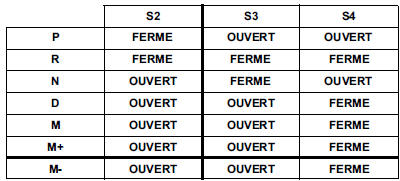
If a status does not work as indicated: apply the fault interpretation:
|
| If ET123, ET124 and ET125 are still incorrect after these checks, replace the multifunction switch. |
AFTER REPAIR
Restart the conformity check from the beginning.
| ET127 | LOWER PADDLE SHIFTER SWITCH |
INSTRUCTIONS
No fault must be present or stored.
| This status shows the state of the lower paddle shifter switch. This status must be "CLOSED" when the selector lever is held in the "M-" position. This status must be "OPEN" when the selector lever is in any position other than "M-". |
| Check the paddle shifter switch supply: +12 V on pin B1 and ground on pin A2 of the paddle shifter switch. |
| Selector lever in "M" position, measure the voltage between: Paddle shifter switch pin B5 → Ground If at least one of the measured values is +12 V, replace the paddle shifter switch. If the values are 0 V, check that the selector lever positions match the display on the instrument panel. |
| If the status does not operate as shown: apply the diagnostic procedure for DTC DF093 "Manual pulse control circuit". |
| If the fault persists, contact your Techline. |
AFTER REPAIR
Restart the conformity check from the beginning
| ET128 | UPPER PADDLE SHIFTER SWITCH |
INSTRUCTIONS
No fault must be present or stored.
| This status shows the state of the upper paddle shifter switch. This status must be "CLOSED" when the selector lever is in the "M+" position. This status must be "OPEN" when the selector lever is in any position other than "M+". |
| Check the paddle shifter switch supply: +12 V on pin B1 and ground on pin A2 of the paddle shifter switch. |
| Selector lever in "M" position, measure the voltage between: Paddle shifter switch pin B5 → Ground If at least one of the measured values is +12 V, replace the paddle shifter switch. If the values are 0 V, check that the selector lever positions match the display on the instrument panel. |
| If the status does not operate as shown: apply the diagnostic procedure for DTC DF093 "Manual pulse control circuit". |
| If the fault persists, contact your Techline. |
AFTER REPAIR
Restart the conformity check from the beginning.
| ET142 | BRAKE PEDAL DEPRESSED |
INSTRUCTIONS
No fault must be present or stored.
| This status shows the position of the brake pedal. The status is "YES" when the brake pedal is pressed. The status is "NO" when the brake pedal is not pressed. |
| If the status does not work as indicated above, apply fault interpretation DF119 "Brake pedal position". |
| Disconnect the ECU. Check the cleanliness and condition of the connector. Use the "Universal breakout box Elé. 1681". Check insulation, continuity and absence of parasitic resistance of the following link: ECU pin 16 → Pin 3 Brake switch |
| If the problem persists, replace the brake sensor. If the fault persists, contact your Techline. |
AFTER REPAIR
Restart the conformity check from the beginning.
| ET157 | SELECTOR LEVER UNLOCK |
INSTRUCTIONS
No fault must be present or stored
| This status shows whether the selector lever is unlocked or not. Lever in "P" position. The status is "YES" when the brake pedal is pressed. The status is "NO" when the brake pedal is not pressed. Lever in a position other than "P". The status is "YES" whether or not the brake pedal is pressed. |
| Check that the lever is in the "P" position on the instrument panel. Check that when the brake pedal is pressed, the message "Press brake pedal" disappears from the instrument panel. |
| Check the operation of the selector lever up to the multifunction switch. Adjust the cable if necessary. |
| Check the correct operation of ET154, ET123, ET124 and ET125 "Multifunction switch". |
| If the status does not work as indicated: apply fault interpretation DF095 "Selector lever lock solenoid circuit". |
| If the fault persists, contact your Techline. |
AFTER REPAIR
Restart the conformity check from the beginning.
Summary table of parameters
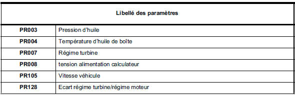
Test yourself
A quick Renault Megane quiz: every answer comes with an explanation and a link to the manual page.