Oil Vapour Recirculation
K4J
I - COMPONENT DESCRIPTION
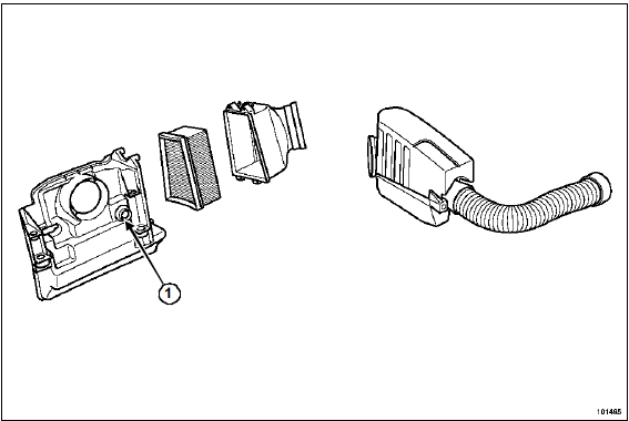
- Oil vapour suction port
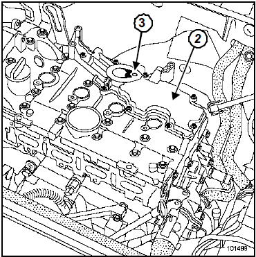
- Oil vapour recovery plate fitted on the rocker cover
- Calibrated orifice
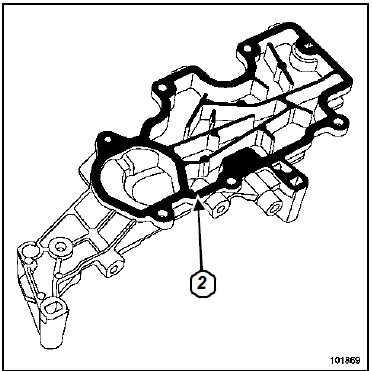
For removal of the oil vapour recovery plate (2), see Upper and Front Engine chapter, page .
II - CIRCUIT DESCRIPTION
A: At low load, oil vapours are drawn in in small quantities through the calibrated orifice (7).
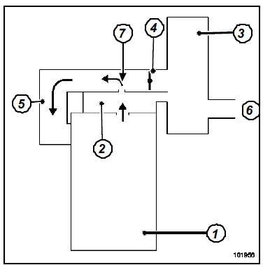
B: At medium and high loads, oil vapours are drawn in in large quantities through the throttle butterfly.
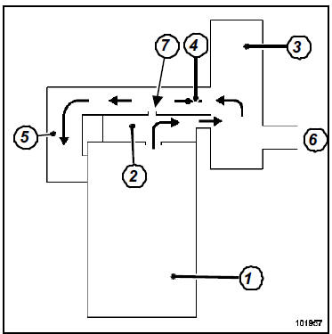
- Engine
- Oil vapour recovery plate
- Air box
- Motorised throttle butterfly
- Air distributor
- Intake air inlet
- Calibrated orifice
III - CHECK
To ensure correct operation of the emission control system, the oil vapour recirculation circuit must be kept clean and in good condition.
K4M
I - COMPONENT DESCRIPTION
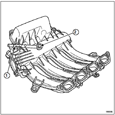
- Oil vapour suction duct
- Calibrated orifice
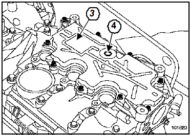
- Oil vapour recovery plate on the rocker cover
- Oil vapour suction port
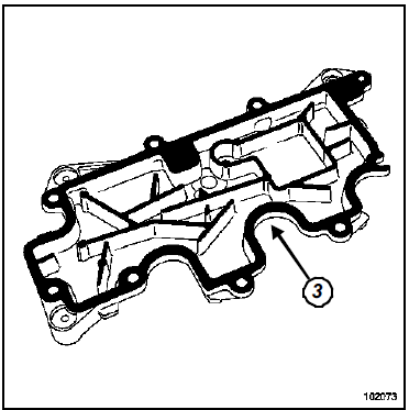
For removal of the oil vapour separator plate (3), see Upper and Front Engine chapter, page .
II - CIRCUIT DESCRIPTION
A: At low load, oil vapours are drawn back in small quantities through the calibrated orifice (6).
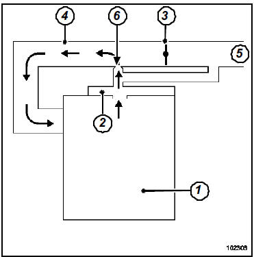
B: At medium and high loads, oil vapours are drawn back in large quantities through the throttle valve.
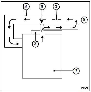
- Engine
- Oil vapour recovery plate
- Motorised throttle butterfly
- Air distributor
- Intake air inlet
- Calibrated orifice
III - CHECK
To ensure correct operation of the emission control system, the oil vapour recirculation circuit must be kept clean and in good condition.
K9K
I - CIRCUIT OVERVIEW
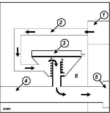
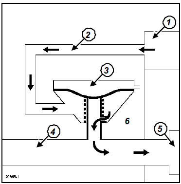
- Rocker cover
- Oil vapour suction duct
- Oil vapour recirculation valve
- Air intake duct
- Turbocharger
- Atmospheric pressure
A: At low load, the vacuum in the air intake duct is lower than the spring calibration.
Oil vapours are drawn back in large quantities by the vacuum in the air intake duct.
B: At medium and high load, the vacuum in the air intake duct pulls the valve diaphragm, and oil vapours are drawn in small quantities through a calibrated orifice.
II - CHECKING
To ensure correct operation of the emission control system, the oil vapour recirculation circuit must be kept clean and in good condition.
F9Q
I - CIRCUIT OVERVIEW
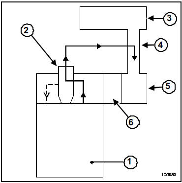
- Engine
- Oil separator
- Air filter housing
- Air duct
- Turbocharger
- Intake manifold
II - CHECKING
To ensure correct operation of the emission control system, the oil vapour recirculation circuit must be kept clean and in good condition.
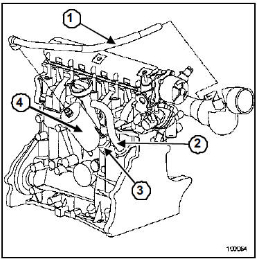
- Oil vapour recirculation hose connected to the intake pipe
- Oil vapour recirculation hose from crankcase outlet to cylinder head
- Oil return hose from the separator
- Oil separator
F4R
I - COMPONENT DESCRIPTION
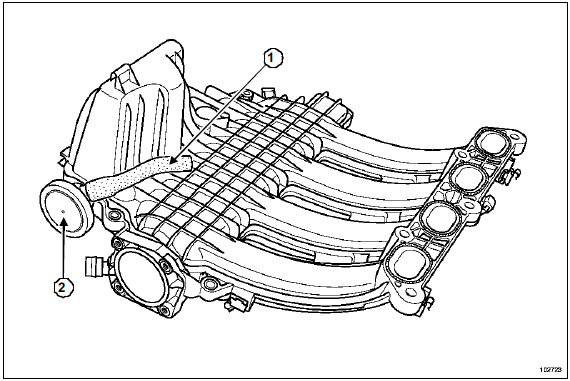
- Oil vapour suction duct
- Oil vapour recirculation check valve
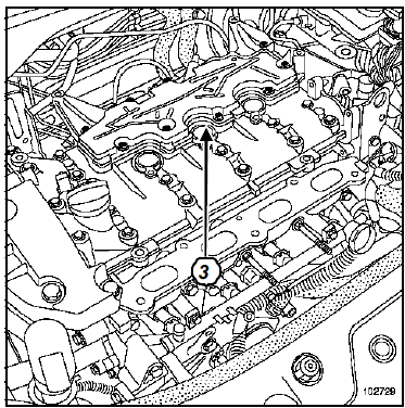
- Oil vapour recovery plate on the rocker cover
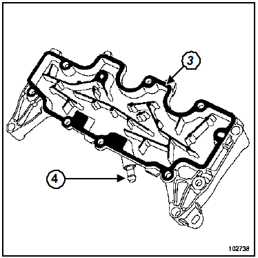
- Oil vapour recirculation orifice upstream of throttle valve
For removal, see Upper and Front Engine chapter.
II - OIL VAPOUR RECIRCULATION CIRCUIT
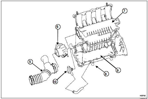
- Air duct
- Throttle body
- Intake manifold
- Oil vapour recirculation orifice upstream of throttle valve
- Oil vapour recovery plate
- Oil vapour recirculation check valve
III - CHECK
To ensure correct operation of the emission control system, the oil vapour recirculation circuit must be kept clean and in good condition.
Test yourself
A quick Renault Megane quiz: every answer comes with an explanation and a link to the manual page.