Fuel Vapour Recirculation
PETROL
I - CIRCUIT FUNCTIONAL DIAGRAM
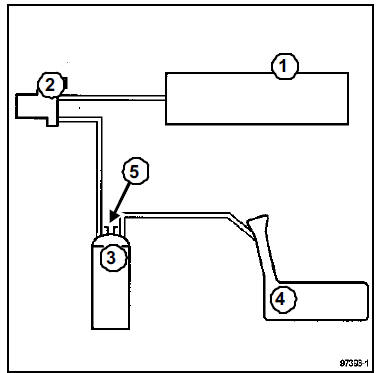
- Intake manifold
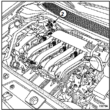
- Fuel vapour canister purge solenoid valve
- Fuel vapour canister
- Reservoir
- Atmospheric vent
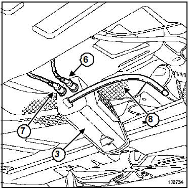
- Fuel vapours recirculation from the fuel tank
- Fuel vapours recirculation to the engine
- Fuel tank atmospheric vent
With the engine running normally, the atmospheric vent must not be blocked.
II - OPERATING PRINCIPLE
The fuel tank is vented through the fuel vapour canister.
Fuel vapours are retained as they pass through the activated charcoal contained in the canister.
The fuel vapours contained in the canister are purged and burned by the engine.
To do this, the solenoid valve connects the fuel vapour canister and the intake manifold.
This solenoid valve is located on the shock absorber turret.
The solenoid valve principle is to provide a variable flow section (depending on the duty cycle signal) sent by the injection computer.
The variable flow section of fuel vapours through the solenoid valve results from the balance between the magnetic field created by energising the coil and the force of the return spring which keeps the solenoid valve closed.
Test yourself
A quick Renault Megane quiz: every answer comes with an explanation and a link to the manual page.