Steering
Steering Column and Shaft Repair Procedures
In this manual: Steering
44steps
~269min
5/5difficulty
1special tools
Done 0 of 44
Removal
[For C-MDPS Type]
|
- Disconnect the negative battery cable from the battery and wait at least 30 seconds.
- Turn the steering wheel so that the front wheels point straight ahead.
- Remove the airbag module.
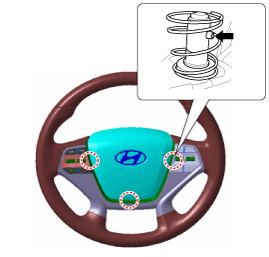
- Remove the DAB module.
- Disconnect the airbag connector (A).
- Disconnect the horn connector (B).
- Remove the clip (C).
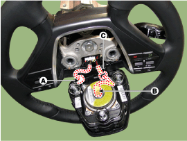
- Loosen the steering wheel lock bolt properly. Separate the steering wheel using SST (09561-11001).
- Fully loosen the steering wheel lock bolt, then remove the steering wheel.
- Remove the steering column covers (A) and (B).
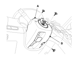
- Disconnect the connector and remove the clock spring (A).
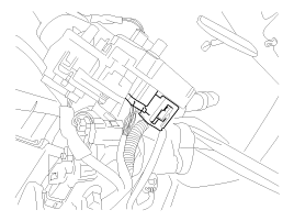
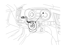
When installing the clock spring, follow the procedure below.
- Press the Auto Lock button at the 6 o'clock position and turn clockwise 3 turns.
- Press the Auto Lock button at the 6 o'clock position and turn counterclockwise 3 turns.
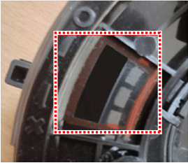
- If the white cable is visible through the 10 o'clock neutral check window, the clock spring is in the neutral position.
Normal Abnormal 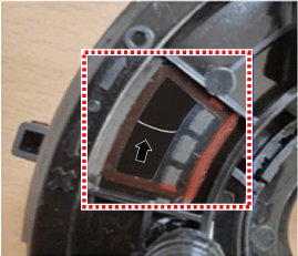
- Disconnect the multifunction switch connector.
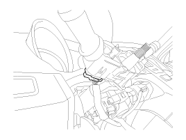
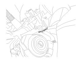
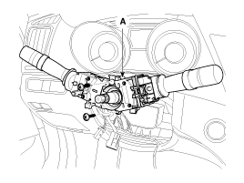
- Loosen the screw and remove the multifunction switches (A).
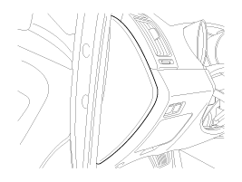
- Remove the lower airbag cover,
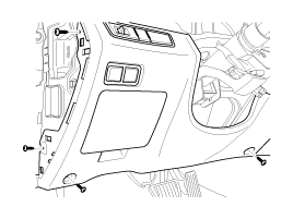
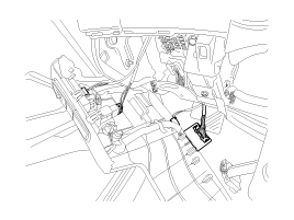
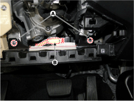
- Loosen the knee bag mounting nut for the AIG (A) and disconnect the connector (B).
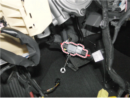
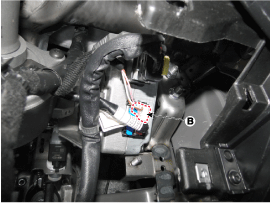
- Disconnect the ECU connectors (A) and (B).
- Disconnect the wiring connected to the steering column assembly.
- Loosen the universal joint bolt (A), then disconnect the universal joint assembly.
Tightening torque: 32.4 ~ 37 N·m
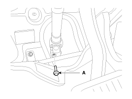
- Lock the steering wheel in the straight-ahead position to prevent damage to the inner cable of the clock spring when handling the steering wheel.
- Do not reuse the bolt.
- Remove the steering column and EPS unit by loosening the mounting bolt (B) and nuts (A). Tightening torque Nut: 25.0 ~ 29 N·m Bolt: 44.1 ~ 49 N·m
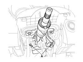
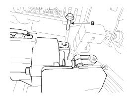
- Installation is the reverse of removal.
- After installation, perform ASP calibration and EPS type recognition.
[For R-MDPS Type]
- Disconnect the negative battery cable from the battery and wait at least 30 seconds.
- Turn the steering wheel so that the front wheels point straight ahead.
- Remove the airbag module.
- Remove the DAB module.
- Disconnect the airbag connector (A).
- Disconnect the horn connector (B).
- Remove the clip (C).
- Loosen the steering wheel lock bolt properly. Separate the steering wheel using SST (09561-11001).
- Fully loosen the steering wheel lock bolt, then remove the steering wheel.
- Remove the steering column covers (A) and (B).
- Disconnect the connector and remove the clock spring (A).
When installing the clock spring, follow the procedure below.- Press the Auto Lock button at the 6 o'clock position and turn clockwise 3 turns.
- Press the Auto Lock button at the 6 o'clock position and turn counterclockwise 3 turns.
- If the white cable is visible through the 10 o'clock neutral check window, the clock spring is in the neutral position.
Normal Abnormal - Disconnect the multifunction switch connector.
- Loosen the screw and remove the multifunction switches (A).
- Remove the lower airbag cover,
- Loosen the knee bag mounting nut for the AIG (A) and disconnect the connector (B).
- Disconnect the wiring connected to the steering column assembly.
- Loosen the universal joint bolt (A), then disconnect the universal joint assembly.
Tightening torque: 32.4 ~ 37 N·m
- Lock the steering wheel in the straight-ahead position to prevent damage to the inner cable of the clock spring when handling the steering wheel.
- Do not reuse the bolt.
- Remove the steering column and EPS unit by loosening the mounting bolt (B) and nuts (A). Tightening torque Nut: 25.0 ~ 29 N·m Bolt: 44.1 ~ 49 N·m
Disassembly
Key Lock Assembly
- Using a punch, make a groove in the head of the special bolts (A).
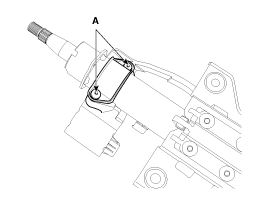
- Loosen the special bolt using a screwdriver, then remove the lock assembly from the steering column assembly.
- Assembly is the reverse of disassembly.
Universal Joint Assembly
- Loosen the bolt (A) and then disconnect the universal joint assembly from the steering column assembly.
Tightening torque: 49.1 ~ 59 N·m
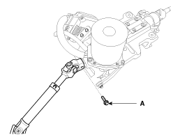
- Assembly is the reverse of disassembly.
- Lock the steering wheel in the straight-ahead position to prevent damage to the inner cable of the clock spring when handling the steering wheel.
- Do not reuse the bolt.
Installation
- Installation is the reverse of removal.
- Connect the scan tool to the diagnostic link connector (16-pin) under the protective cover on the driver's seat side, then turn the ignition on to activate the scan tool.
- In the GDS vehicle type selection menu, select "Vehicle Type" and "EPS System," then select "OK."
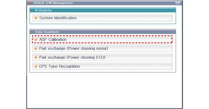
- Select ASP Calibration.
- Continue the test in accordance with the instructions on the screen.
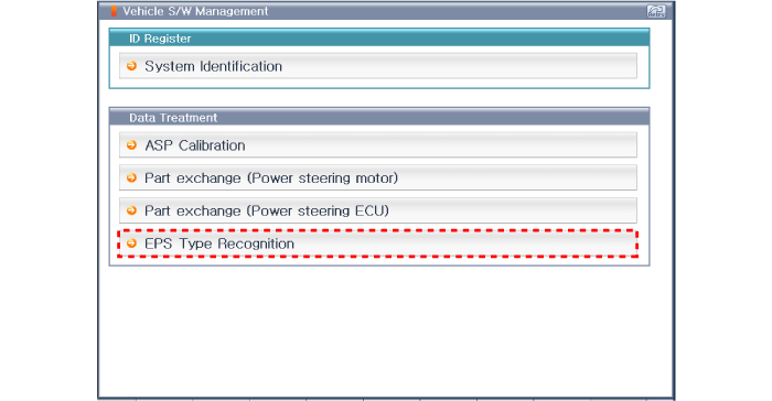
- Select "EPS Variant Coding".
- Continue the test in accordance with the instructions on the screen.
Test yourself
A quick Hyundai Sonata LF quiz: every answer comes with an explanation and a link to the manual page.
Was this page helpful?