Motor LH Current Senser (62,63)
When the side auto step motor current detection sensor inside the side auto step controller ECU assembly detects a current of less than 1 A when the automatic running board is operating, the side auto step controller ECU assembly does not operate the automatic running board.
DTC No. | Detection Condition | Trouble Area |
|---|---|---|
61 |
When the side auto step motor assembly LH is operating, there is less than 1 A of current detected in the side auto step ECU even when the hall effect pluses are input. |
|
62 |
When the side auto step motor assembly RH is operating, there is less than 1 A of current detected in the side auto step ECU even when the hall effect pluses are input. |
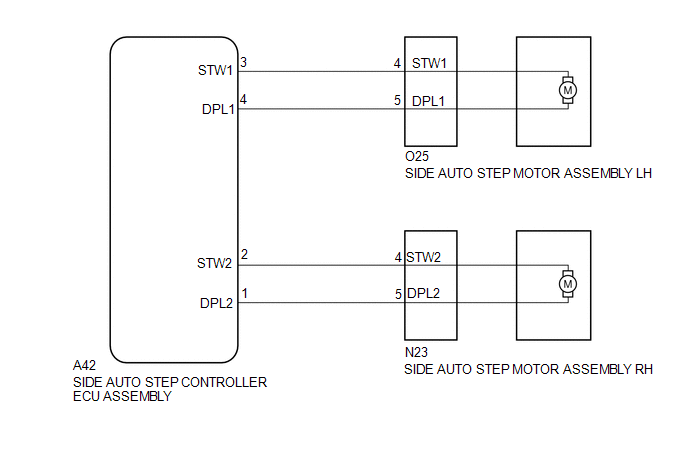
PROCEDURE
CHECK HARNESS AND CONNECTOR (SIDE AUTO STEP MOTOR - SIDE AUTO STEP CONTROLLER ECU)
(a) Disconnect the O25*1 or N23*2 side auto step motor assembly connector.
- *1: for LH
- *2: for RH
(b) Disconnect the A42 side auto step controller ECU assembly connector.
(c) Measure the resistance according to the value(s) in the table below.
Standard Resistance:
for LH
Tester Connection | Condition | Specified Condition |
|---|---|---|
O25-4 (STW1) - A42-3 (STW1) |
Always |
Below 1 Ω |
O25-5 (DPL1) - A42-4 (DPL1) |
Always |
Below 1 Ω |
for RH
Tester Connection | Condition | Specified Condition |
|---|---|---|
N23-4 (STW2) - A42-2 (STW2) |
Always |
Below 1 Ω |
N23-5 (DPL2) - A42-1 (DPL1) |
Always |
Below 1 Ω |
| NG |  | REPAIR OR REPLACE HARNESS OR CONNECTOR |
|

PERFORM COOL DOWN
(a) Do not operate the automatic running board in order to cool down the side auto step motor assembly.
|
CHECK DTC
(a) Recheck for DTCs and check if the same DTC is output again.
OK:
No DTCs are output.
| OK | | END |
| NG | | REPLACE SIDE AUTO STEP CONTROLLER ECU ASSEMBLY |
Test yourself
A quick Toyota 4Runner quiz: every answer comes with an explanation and a link to the manual page.