Front Stabilizer Bar
Components
COMPONENTS
ILLUSTRATION
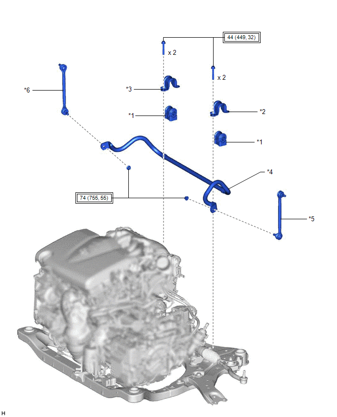
*1 |
FRONT NO. 1 STABILIZER BAR BUSHING |
*2 |
FRONT NO. 1 STABILIZER BRACKET LH |
*3 |
FRONT NO. 1 STABILIZER BRACKET RH |
*4 |
FRONT STABILIZER BAR |
*5 |
FRONT STABILIZER LINK ASSEMBLY LH |
*6 |
FRONT STABILIZER LINK ASSEMBLY RH |
 |
Tightening torque for "Major areas involving basic vehicle performance such as moving/turning/stopping": N*m (kgf*cm, ft.*lbf) |
- |
- |
Inspection
INSPECTION
PROCEDURE
1. INSPECT FRONT STABILIZER LINK ASSEMBLY
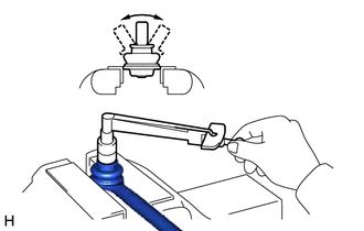
(a) Inspect the turning torque of the ball joint. (1) Secure the front stabilizer link assembly in a vise using aluminum plates. NOTICE: Do not overtighten the vise. (2) Install the nut to the front stabilizer link assembly stud. (3) Using a torque wrench, turn the stud continuously at a rate of 3 to 5 seconds per turn and take the torque reading on the 5th turn. Turning Torque: 0.05 to 1.96 N*m (0.6 to 19 kgf*cm, 0.5 to 17 in.*lbf) HINT: If the turning torque is not within the specified range, replace the front stabilizer link assembly with a new one. (4) Turn the stud to check that the stud does not catch and there is no play. HINT: If the stud catches or there is play while turning, replace the front stabilizer link assembly with a new one. |
 |
(b) Inspect the dust cover.
(1) Check that the dust cover is not cracked and that there is no grease on it.
HINT:
If the dust cover is cracked or there is grease on it, replace the front stabilizer link assembly with a new one.
Installation
INSTALLATION
PROCEDURE
1. INSTALL FRONT NO. 1 STABILIZER BAR BUSHING (for LH Side)
(a) Install the front No. 1 stabilizer bar bushing to the front stabilizer bar as shown in the illustration.
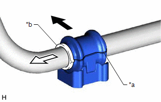
*a |
Cutout |
*b |
Stopper Ring |
 |
Front of the Vehicle |
 |
Outside of the Vehicle |
NOTICE:
- Install the front No. 1 stabilizer bar bushing so that the cutout is facing the rear of the vehicle.
- Install the front No. 1 stabilizer bar bushing onto the front stabilizer bar so that the stopper ring of the front stabilizer bar faces the outside of the vehicle.
2. INSTALL FRONT NO. 1 STABILIZER BAR BUSHING (for RH Side)
HINT:
Perform the same procedure as for the LH side.
3. INSTALL FRONT STABILIZER BAR
(a) Install the front stabilizer bar with the 2 front stabilizer bar bushings to the front frame assembly.
NOTICE:
Make sure that the identification mark is positioned as shown in the illustration.
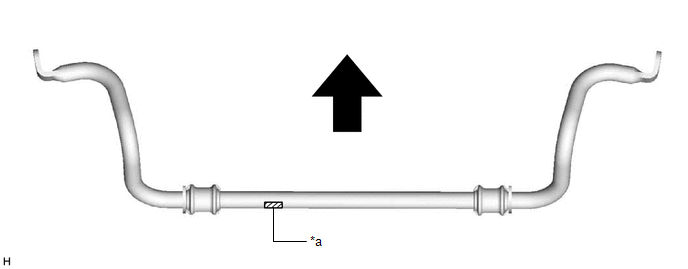
*a |
Identification Mark |
- |
- |
|
Front of the Vehicle |
- |
- |
4. INSTALL FRONT NO. 1 STABILIZER BRACKET LH
(a) Install the front No. 1 stabilizer bracket LH to the front frame assembly with the 2 bolts.
Torque:
44 N·m {449 kgf·cm, 32 ft·lbf}
NOTICE:
- Make sure to install the front No. 1 stabilizer bracket LH with its arrow facing the front of the vehicle.
- Temporarily tighten the bolt (B) and then fully tighten the 2 bolts in the order of (A) and (B).
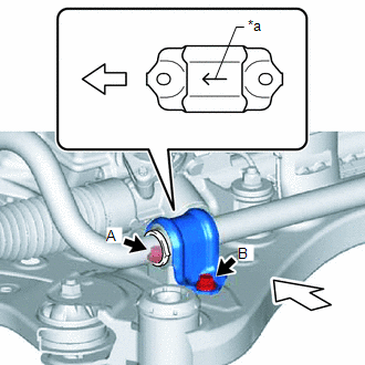
*a |
Arrow |
|
Front of the Vehicle |
5. INSTALL FRONT NO. 1 STABILIZER BRACKET RH
HINT:
Perform the same procedure as for the LH side.
6. INSTALL FRONT STABILIZER LINK ASSEMBLY LH
(a) Install the front stabilizer link assembly LH to the front stabilizer bar with the nut.
Torque:
74 N·m {755 kgf·cm, 55 ft·lbf}
NOTICE:
Do not damage the boot of the ball joint.
HINT:
If the ball joint turns together with the nut, use a 6 mm hexagon socket wrench to hold the stud bolt.
7. INSTALL FRONT STABILIZER LINK ASSEMBLY RH
HINT:
Perform the same procedure as for the LH side.
8. INSTALL ENGINE ASSEMBLY WITH TRANSAXLE
for HV Model: Click here 
for Gasoline Model: Click here
Removal
REMOVAL
The necessary procedures (adjustment, calibration, initialization, or registration) that must be performed after parts are removed and installed, or replaced during front stabilizer bar removal/installation are shown below.
Necessary Procedures After Parts Removed/Installed/Replaced (for HV Model:)Replaced Part or Performed Procedure | Necessary Procedure | Effect/Inoperative Function when Necessary Procedure not Performed | Link |
|---|---|---|---|
Auxiliary battery terminal is disconnected/reconnected |
Perform steering sensor zero point calibration |
Lane departure alert system (w/ Steering Control) |
 |
Pre-collision system |
|||
Intelligent clearance sonar system* |
|||
Lighting system (for HV Model with Cornering Light) |
|||
Memorize steering angle neutral point |
Parking assist monitor system |
|
|
Panoramic view monitor system |
|
||
Replacement of ECM |
Vehicle Identification Number (VIN) registration |
MIL illuminates |
|
|
Inspection After Repair |
|
|
Replacement of inverter with converter assembly |
Resolver learning |
|
|
Replacement of hybrid vehicle transaxle assembly |
|
||
Front wheel alignment adjustment |
|
|
|
|
|
|
|
Suspension, tires, etc. (The vehicle height changes because of suspension or tire replacement) |
Rear television camera assembly optical axis (Back camera position setting) |
Parking assist monitor system |
for Initialization: for Calibration: |
Replacement of front bumper assembly |
Front television camera view adjustment |
Panoramic view monitor system |
for Initialization: for Calibration: |
Suspension, tires, etc. (The vehicle height changes because of suspension or tire replacement) |
|
||
|
Synchronize the vehicle information |
Lighting system (for HV Model with Cornering Light) |
|
Rack and pinion power steering gear assembly |
|
|
|
*: When performing learning using the Techstream.
Click here
Replaced Part or Performed Procedure | Necessary Procedure | Effect/Inoperative Function when Necessary Procedure not Performed | Link |
|---|---|---|---|
Battery terminal is disconnected/reconnected |
Perform steering sensor zero point calibration |
Lane departure alert system (w/ Steering Control) |
|
Pre-collision system |
|||
Intelligent clearance sonar system*1 |
|||
Lighting system (for Gasoline Model with Cornering Light) |
|||
Memorize steering angle neutral point |
Parking assist monitor system |
|
|
Panoramic view monitor system |
|
||
Replacement of ECM |
Vehicle Identification Number (VIN) registration |
MIL comes on |
|
Perform code registration (Immobiliser system) |
Engine start function |
|
|
|
Inspection after repair |
|
|
Replacement of automatic transaxle assembly |
|
|
for Initialization: for Registration: |
Replacement of ECM (If transaxle compensation code read from ECM) |
|
||
Replacement of ECM (If transaxle compensation code not read from ECM) |
|
||
Replacement of automatic transaxle fluid |
ATF thermal degradation estimate reset |
The value of the Data List item "ATF Thermal Degradation Estimate" is not estimated correctly |
|
Replacement of ECM |
Code registration (Smart Key System (for Start Function)) |
|
|
Suspension, tires, etc. |
|
|
|
Rear television camera assembly optical axis adjustment (Back camera position setting) |
Parking Assist Monitor System |
for Initialization: for Calibration: |
|
|
Panoramic View Monitor System |
for Initialization: for Calibration: |
|
Perform headlight ECU sub-assembly LH initialization |
Lighting system (for Gasoline Model with Cornering Light) |
|
|
Front wheel alignment adjustment |
Perform system variant learning and acceleration sensor zero point calibration. |
|
|
Rack and pinion power steering gear assembly |
|
|
|
*1: When performing learning using the Techstream.
Click here
*2: Not necessary when ECM replaced with new one
PROCEDURE
1. REMOVE ENGINE ASSEMBLY WITH TRANSAXLE
for HV Model: Click here
for Gasoline Model: Click here
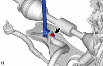
2. REMOVE FRONT STABILIZER LINK ASSEMBLY LH
(a) Remove the nut and front stabilizer link assembly LH from the front stabilizer bar. NOTICE: Do not damage the boot of the ball joint. HINT: If the ball joint turns together with the nut, use a 6 mm hexagon socket wrench to hold the stud bolt. |
 |
3. REMOVE FRONT STABILIZER LINK ASSEMBLY RH
HINT:
Perform the same procedure as for the LH side.
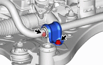
4. REMOVE FRONT NO. 1 STABILIZER BRACKET LH
(a) Remove the 2 bolts and front No. 1 stabilizer bracket LH from the front frame assembly. |
 |
5. REMOVE FRONT NO. 1 STABILIZER BRACKET RH
HINT:
Perform the same procedure as for the LH side.
6. REMOVE FRONT STABILIZER BAR
(a) Remove the front stabilizer bar with 2 front stabilizer bar bushings from the front frame assembly.
7. REMOVE FRONT NO. 1 STABILIZER BAR BUSHING (for LH Side)
(a) Remove the front No. 1 stabilizer bar bushing from the front stabilizer bar.
8. REMOVE FRONT NO. 1 STABILIZER BAR BUSHING (for RH Side)
HINT:
Perform the same procedure as for the LH side.