K114 Continuously Variable Transmission
Disassembly
In this manual: K114 Continuously Variable Transmission
~1min read
DISASSEMBLY
PROCEDURE
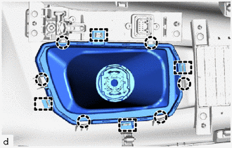
1. REMOVE SHIFT LEVER HOLE COVER SUB-ASSEMBLY
(a) Release the 4 guides and 6 claws to remove the shift lever hole cover sub-assembly from the console upper panel sub-assembly. |
 |
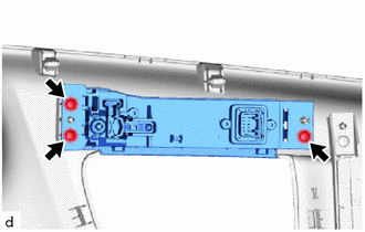
2. REMOVE SHIFT POSITION INDICATOR
(a) Remove the 3 screws and the shift position indicator from the console upper panel sub-assembly. |
 |
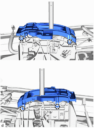
3. REMOVE SHIFT LEVER HOUSING SUPPORT SUB-ASSEMBLY
(a) Release the 4 claws to remove the shift lever housing support sub-assembly from the shift lock control unit assembly. |
 |
Was this page helpful?