Buzzer Assembly
Components
COMPONENTS
ILLUSTRATION
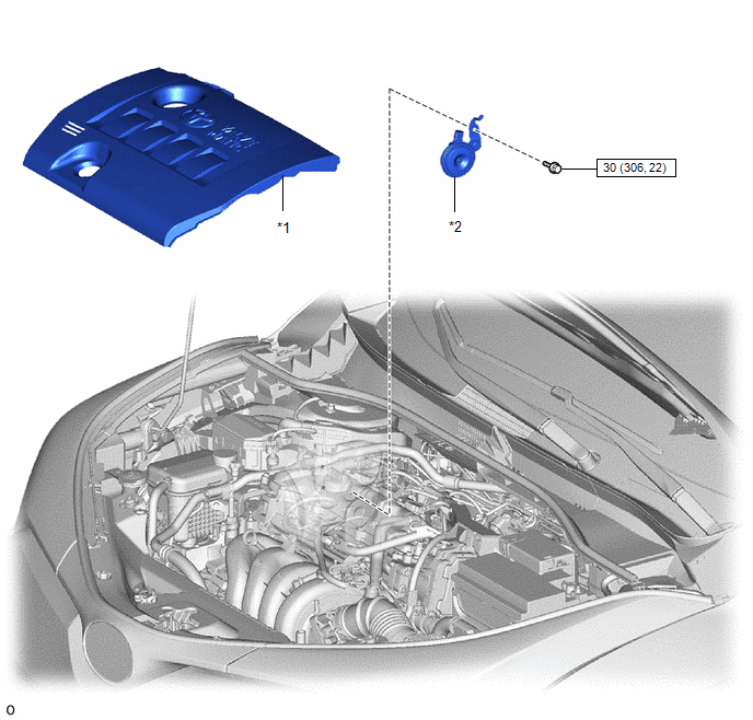
*1 |
NO. 2 VALVE COVER |
*2 |
BUZZER ASSEMBLY |
 |
N*m (kgf*cm, lbf*in): Specified torque |
- |
- |
Removal
REMOVAL
PROCEDURE
1. REMOVE NO. 2 CYLINDER HEAD COVER
Click here
2. REMOVE BUZZER ASSEMBLY
(a) Remove the bolt. |
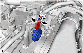 |
(b) Release the guide to remove the buzzer assembly.
(c) Disconnect the connector.
Inspection
INSPECTION
PROCEDURE
1. INSPECT BUZZER ASSEMBLY
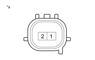
(a) Check operation. (1) Apply battery voltage and check the operation of the buzzer assembly. OK:
If the result is not as specified, replace the buzzer assembly. |
|
Installation
INSTALLATION
PROCEDURE
1. INSTALL BUZZER ASSEMBLY
(a) Connect the connector. |
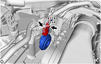 |
(b) Engage the guide to install the buzzer assembly.
(c) Install the bolt.
Torque:
30 N·m {306 kgf·cm, 22 ft·lbf}
2. INSTALL NO. 2 VALVE COVER
Click here