Air conditioning system
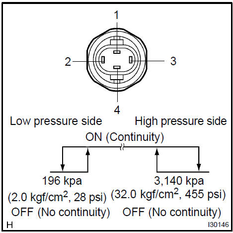
a. Magnetic clutch control: Inspect pressure switch operation.
- Set on the manifold gauge set.
- Connect the positive (+) lead from the ohmmeter to terminal 4 and the negative (−) lead to terminal 1.
- Check continuity between terminals when refrigerant pressure is changed, as shown in the illustration.
If operation is not as specified, replace the pressure switch.
b. Cooling fan control: Inspect pressure switch operation.
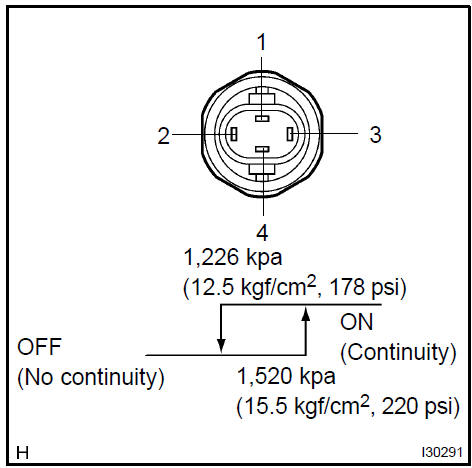
- Connect the positive (+) lead from the ohmmeter to terminal 2 and the negative (−) lead to terminal 3.
- Check continuity between terminals when refrigerant pressure is changed, as shown in the illustration.
If operation is not as specified, replace the pressure switch.
a. Disconnect the connector from controller and inspect the connector on wire harness side, as shown in the chart below.
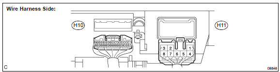
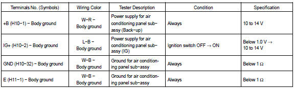
b. Connect the connector to heater controller and inspect wire harness side from the back side, as shown in the chart below.
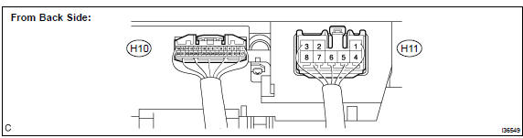
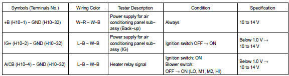
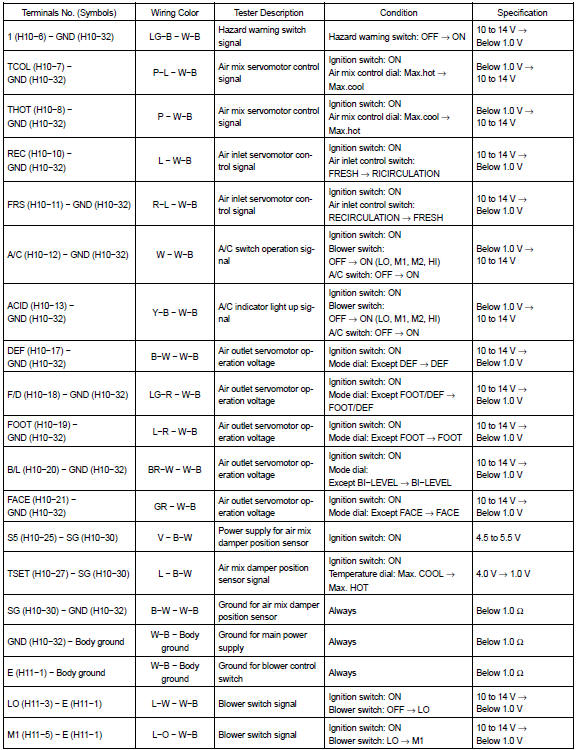

If circuit is as specified, replace the controller with a new one. If the circuit is not as specified, inspect the circuits connected to other parts.
3. INSPECT AIR CONDITIONING AMPLIFIER (2AZ−FE)a. Disconnect the connector from controller and inspect the connector on wire harness side, as shown in the chart below.
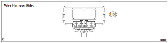

b. Connect the connector to air conditioning amplifier and inspect wire harness side from the back side, as shown in the chart below.
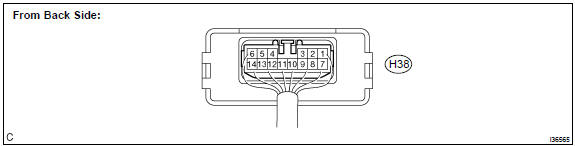

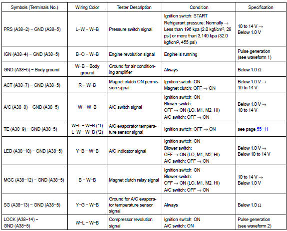
If circuit is as specified, replace the controller with a new one. If the circuit is not as specified, inspect the circuits connected to other parts.
4. INSPECT ECM (1MZ−FE, 3MZ−FE)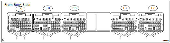
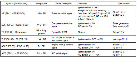
If circuit is as specified, replace the controller with a new one. If the circuit is not as specified, inspect the circuits connected to other parts.
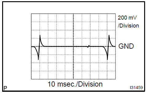
waveform 1: Measure the waveform between terminal IGN of the A/C amplifier assy connector and body ground.OK: A waveform should be output as shown in the illustration.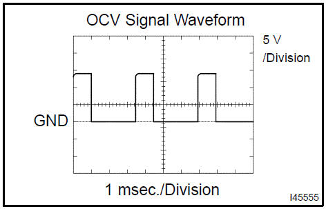

Test yourself
A quick Toyota Camry quiz: every answer comes with an explanation and a link to the manual page.