Air conditioning system
- Connect the positive (+) lead from the battery to terminal 3 and the negative (−) lead to the body ground.
- Check that the magnet clutch energized.
If operation is not as specified, replace the magnet clutch assy.
c. Measure resistance between terminals 1 and 2.Standard resistance: 165 − 205 W at 20 C (68 F)If resistance is not as specified, replace the cooler compressor assy.
 Cooler compressor assy 2. MAGNET−CLUTCH RELAY

If continuity is not as specified, replace the magnet−clutch relay.
 Magnet-clutch relay 3. AIRMIX DAMPER SERVO SUB−ASSY
a. Inspect servomotor operation.
- Connect the positive (+) lead from the battery to terminal 4 and negative (−) lead to terminal 5, then check that the arm turns to ”COLD” side smoothly.
- Connect the positive (+) lead from the battery to terminal 5 and negative (−) lead to terminal 4, then check that the arm turns to ”HOT” side smoothly.
If operations are not as specified, replace the air mix servomotor.
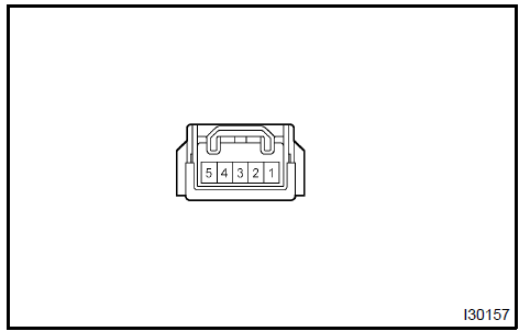
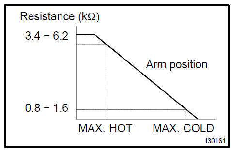
Measure resistance between terminals at servomotor arm each position as shown in the chart.

If resistance is not as specified, replace the servomotor.

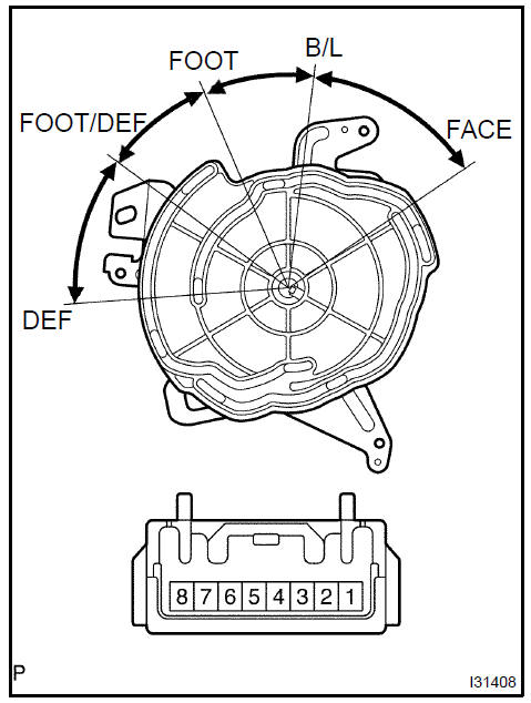
a. Inspect servomotor operation.
- Connect the positive (+) lead from the battery to terminal 7 and the negative (−) lead to terminal 8.
- Connect the negative (−) lead from the battery to each terminal as shown in the chart, and check that the shaft rotates at each position, as shown in the illustration.
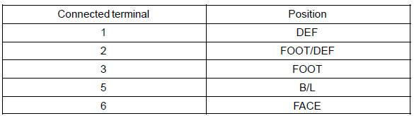
If operation is not as specified, replace the servomoto
 Mode damper servo sub-assy 5. RECIRCULATION DAMPER SERVO SUB−ASSY
a. Inspect servomotor operation.
- Connect the positive (+) lead from the battery to terminal 5 and negative (−) lead to terminal 1, then check that the arm turns to ”REC” side smoothly.
- Connect the positive (+) lead from the battery to terminal 5 and negative (−) lead to terminal 2, then check that the arm turns to ”FRS” side smoothly.
If operations are not as specified, replace the mode damper servomotor.
 Recirculation damper servo sub-assy 6. COOLER THERMISTOR No.1
- Remove cooler thermistor No.1.
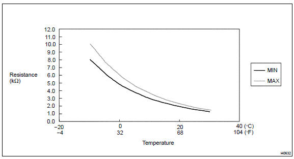
- Check resistance between terminals 1 and 2 of cooler thermistor No.1 at each temperature, as shown in the chart.
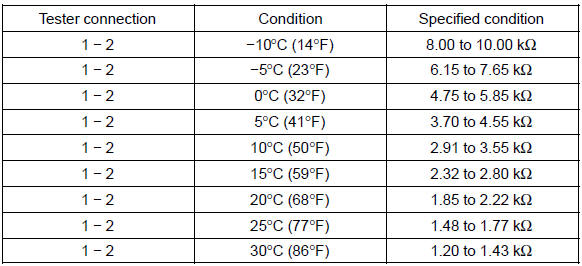
HINT: As the temperature increases, the resistance decreases (see the chart below).

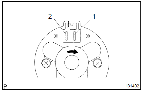
a. Connect the positive (+) lead from the battery to terminal 2 and negative (−) to terminal 1, then check that the motor operation smoothly.
If operation is not as specified, replace the blower motor.
 Blower w/fan motor sub-assy 8. BLOWER RESISTOR
a. Measure resistance between terminals, as shown in the chart below.

If resistance is not as specified, replace the blower resistor.
 Blower resistor 9. HEATER BLOWER MOTOR RELAY ASSY
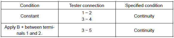
If continuity is not as specified, replace the heater blower motor relay
 Heater blower motor relay assy
Test yourself
A quick Toyota Camry quiz: every answer comes with an explanation and a link to the manual page.