Replacement
: components:
1. Place front wheels facing straight ahead 2. Remove front wheels 3. Remove engine under cover lh 4. Remove engine under cover rh 5. Remove exhaust pipe 6. Drain transaxle oil 7. Remove hood sub–assy 8. Remove cylinder head cover no.2 9. Remove air cleaner assy 10. Remove battery clamp sub–assy 11. Remove battery 12. Remove battery tray 13. Remove battery carrier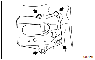
- Remove the 4 bolts and battery carrier.
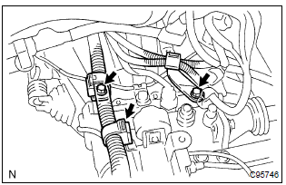
- Disconnect the wire harness clamp.
- remove the 2 bolts and disconnect the 2 wire harness brackets.
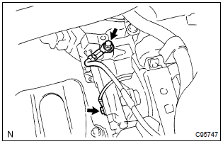
- Remove the 2 bolts and 2 ground cables.
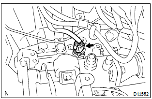
- Disconnect the back–up lamp switch connector.
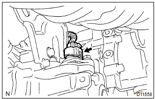
- W/o abs: disconnect the speed sensor connector.
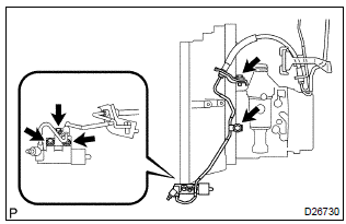
- Remove the 5 bolts, separate the release cylinder assy with clutch piping from the transaxle.
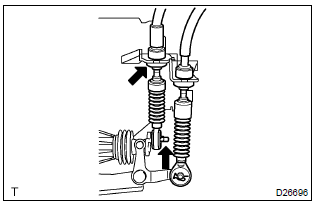
- Remove the clip, washer and disconnect the shift cable from the transaxle.
- remove the clip and disconnect the shift cable from the bracket.
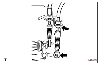
- Remove the clip, washer and disconnect the select cable from the transaxle.
- remove the clip and disconnect the select cable from the bracket.
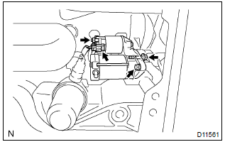
- Remove the nut and disconnect the starter wire.
- disconnect the connector.
- remove the 2 bolts and starter assy.
sst 09520–01010, 09520–24010 (09520–32040)
23. Remove front drive shaft assy rh Hint: remove the rh side by the same procedures as lh side.
Sst 09520–01010, 09520–24010 (09520–32040) 24. Separate return tube sub–assysst 09023–12700
25. Separate pressure feed tube assy 26. Suspend engine assy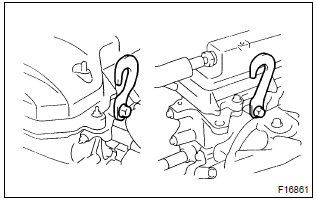
- Remove the 2 pcv hoses.
- install the 2 hangers in the correct direction.
Parts no.:
Engine hanger: 12281–22021 no.1 Engine hanger: 12281–15040 bolt: 91512–b1016
torque: 38 nvm (387 Kgf·cm, 28 ft·lbf) - attach the engine chain hoist to the hangers.
: do not attempt to hang the engine by hooking the chain to any other part.
27. Remove front suspension crossmember sub–assy 28. Support manual transaxle assy- support the transaxle with a transmission jack.
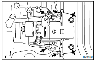
- Remove the 5 bolts, nut and engine mounting insulator lh from the body.
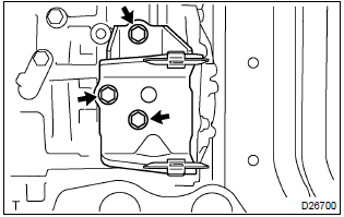
- Remove the 3 bolts and engine mounting bracket lh from the transaxle.
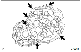
- Remove the 6 bolts and transaxle from the engine.
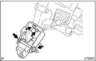
- Remove the bolt, nut and engine mounting insulator fr from the engine mounting bracket fr.
- remove the 2 bolts and engine mounting bracket fr from the transaxle.
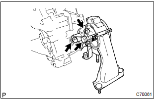
- Remove the bolt and engine mounting insulator rr from the engine mounting bracket rr.
- remove the 3 bolts and engine mounting bracket rr from the transaxle.
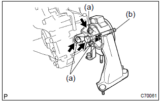
- Install the engine mounting bracket rr and 3 bolts to the transaxle.
Torque: 64 nvm (653 Kgf·cm, 47 ft·lbf)
- install the engine mounting insulator rr and bolt to the engine mounting bracket rr.
Torque: 87 nvm (888 Kgf·cm, 64 ft·lbf)
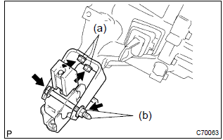
- Install the engine mounting bracket fr and 2 bolts to the transaxle.
Torque: 64 nvm (653 Kgf·cm, 47 ft·lbf)
- install the engine mounting insulator fr, bolt and nut to the engine mounting bracket fr.
Torque: 52 nvm (530 Kgf·cm, 38 ft·lbf)
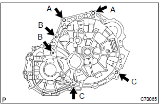
- Align the input shaft with the clutch disc and install the transaxle to the engine.
- install the 6 bolts.
Torque:
bolt a: 64 nvm (650 Kgf·cm, 47 ft·lbf) bolt b: 47 nvm (480 Kgf·cm, 35 ft·lbf) bolt c: 23 nvm (230 Kgf·cm, 17 ft·lbf)
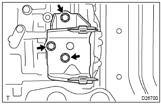
- Install the engine mounting bracket lh to the transaxle with the 3 bolts.
Torque: 52 nvm (530 Kgf·cm, 38 ft·lbf)
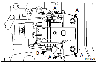
- Install the engine mounting insulator lh with the 5 bolts and nut.
Torque:
bolt a: 52 nvm (530 Kgf·cm, 38 ft·lbf) bolt b: 80 nvm (816 Kgf·cm, 59 ft·lbf)
sst 09670–00010
40. Connect steering intermediate shaft 41. Install column hole cover silencer sheet 42. Connect return tube sub–assysst 09023–12700
43. Connect pressure feed tube assysst 09023–12700
44. Install front drive shaft assy lh 45. Install front drive shaft assy rh Hint: install the rh side by the same procedures as lh side.
46. Install starter assy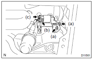
- Install the starter assy and 2 bolts to the transaxle.
Torque: 37 nvm (378 Kgf·cm, 27 ft·lbf)
- connect the starter connector.
- install the wire and nut to starter assy.
Torque: 9.8 Nvm (100 Kgf·cm, 87 in.Vlbf)
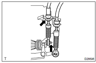
- Connect the shift cable end, and install the washer and clip.
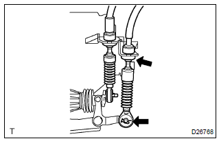
- Connect the select cable end, and install the washer and clip.
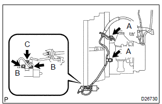
- Install the release cylinder with the 5 bolts.
Torque:
bolt a: 25 nvm (250 Kgf·cm, 19 ft·lbf) bolt b: 12 nvm (120 Kgf·cm, 9 ft·lbf) bolt c: 5.0 Nvm (51 Kgf·cm, 44 in.Vlbf)
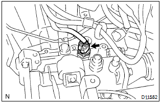
- Connect the back–up lamp switch connector.
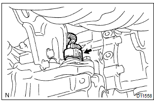
- W/o abs: connect the speed sensor connector.
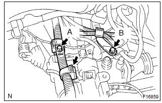
- Install the 2 wire harness clamps to the transaxle with the 2 bolts.
Torque:
bolt a: 25.5 Nvm (260 Kgf·cm, 19 ft·lbf) bolt b: 12.8 Nvm (131 Kgf·cm, 9 ft·lbf) - connect the wire harness clamp.
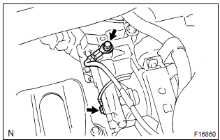
- Install the 2 bolts and 2 ground cables.
Torque: 13 nvm (133 Kgf·cm, 10 ft·lbf)
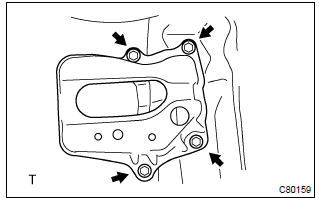
- Install the battery carrier and 4 bolts.
Torque: 13 nvm (133 Kgf·cm, 10 ft·lbf)
Torque:
bolt: 5.0 Nvm (51 Kgf·cm, 44 in.Vlbf) nut: 3.5 Nvm (36 Kgf·cm, 31 in.Vlbf)
torque: 7.0 Nvm (71 Kgf·cm, 62 in.Vlbf)
58. Install cylinder head cover no.2Torque: 7.0 Nvm (71 Kgf·cm, 62 in.Vlbf)
59. Install hood sub–assytorque: 13 nvm (133 Kgf·cm, 10 ft·lbf)
60. Inspect hood sub–assy 61. Adjust hood sub–assy 62. Add transaxle oil 63. Inspect transaxle oil 64. Bleed power steering fluid 65. Install front wheelstorque: 103 nvm (1,050 Kgf·cm, 76 ft·lbf)
66. Place front wheels facing straight ahead 67. Install exhaust pipe 68. Install engine under cover lh 69. Install engine under cover rh 70. Inspect front wheel alignment 71. Check abs speed sensor signalTest yourself
A quick Toyota Corolla quiz: every answer comes with an explanation and a link to the manual page.