Discharge fuel system pressure procedures must be performed before disconnecting any part of the fuel system.
After performing the discharge fuel system pressure procedures, pressure will remain in the fuel line. When disconnecting the fuel line, place a cloth or equivalent over fittings to reduce the risk of fuel spray.
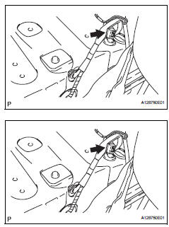
Remove the console box (see page ir-83).
Disconnect the connector.
Start the engine. After the engine has stopped, turn the ignition switch off.
Hint:
Dtc p0171 (system too lean) may be set.
Check that the engine does not start.
Remove the fuel tank cap, and let the air out of the fuel tank.
Connect the connector.
Install the console box (see page ir-90).
Disconnect cable from negative battery terminal
Caution:Wait at least 90 seconds after disconnecting the cable from the negative (-) battery terminal to prevent airbag and seat belt pretensioner activation.
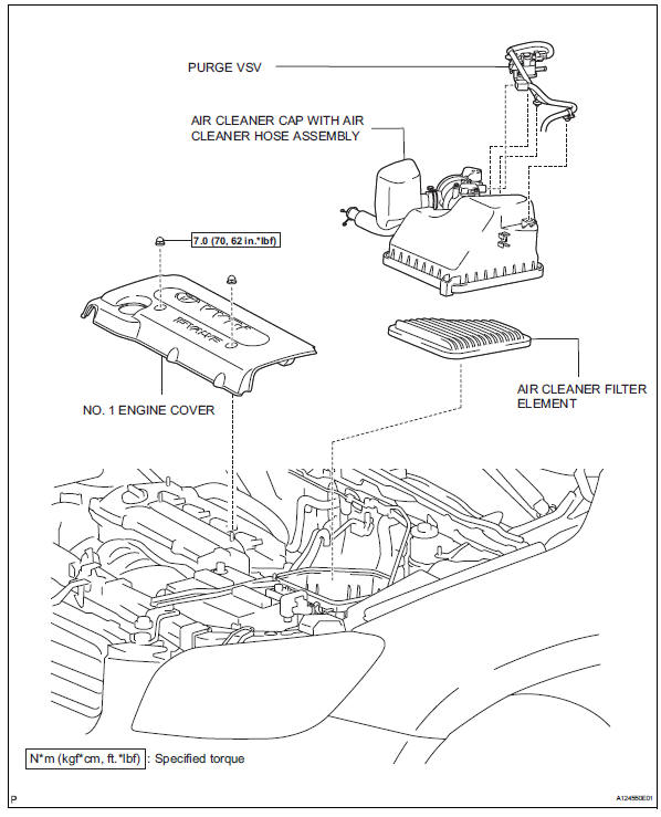
Remove no. 1 Engine cover (see page es-410)
Remove air cleaner cap sub-assembly (see page es-411)
Disconnect fuel main tube
Notice:
Do not forcibly bend and twist the fuel main tube.
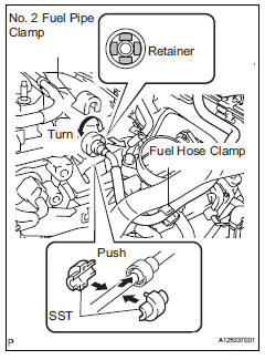
Remove the fuel tube from the fuel hose clamp.
Remove the fuel pipe clamp.
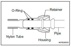
Wipe off any dirt on the fuel tube connector.
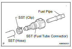
Hold the fuel tube connector, and then install sst.
Sst 09268-21010
Turn sst to align the retainer inside the fuel tube connector with the chamfered part of sst.
Insert sst into the fuel tube and hold it. Then push the fuel tube connector toward sst side.
Mount the retainer of the fuel tube connector onto the chamfered part of sst.
Slide sst and fuel tube connector together towards the fuel tube until they make a "click" sound, and then disconnect the fuel tube.
Drain the fuel remaining inside the fuel tube.
Cover the fuel tube and fuel pipe with a plastic bag to protect the disconnected part.
Disconnect no. 2 ventilation hose
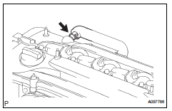
Disconnect the no. 2 Ventilation hose from the ventilation valve.
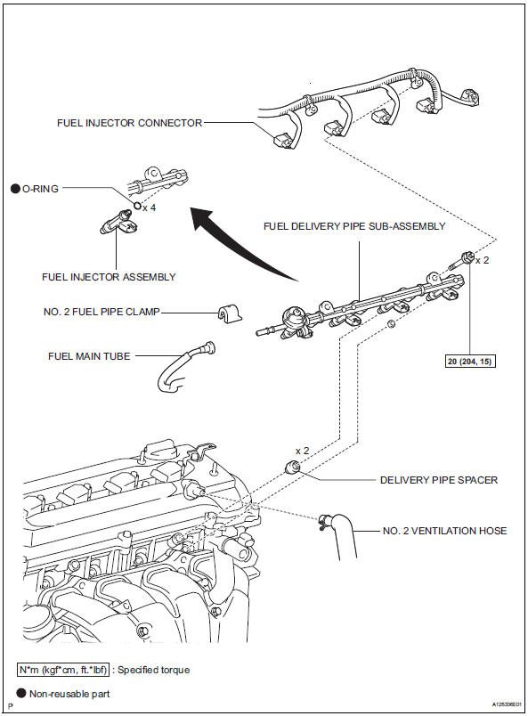
Remove fuel delivery pipe sub-assembly
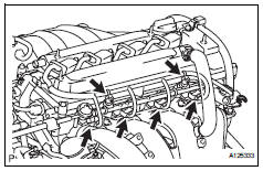
Remove the 2 wire harness clamps.
Disconnect the 4 fuel injector connectors.
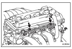
Remove the 2 bolts, then remove the fuel delivery pipe together with the 4 fuel injectors.
Notice:
Be careful not to drop the fuel injectors when removing the fuel delivery pipe.
Remove the 2 delivery pipe spacers from the cylinder head.
Remove the 4 insulators from the cylinder head.
Remove fuel injector assembly
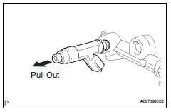
Pull the 4 fuel injectors out of the fuel delivery pipe.
Inspection
Inspect fuel injector assembly
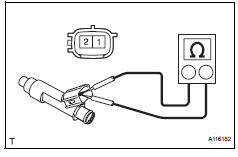
Measure the resistance between the injector terminals.
Standard resistance: 11.6 To 12.4 Ù at 20°c (68°f)
If the result is not as specified, replace the injector.
Inspect the injector injection.
Caution:Keep the injector away from sparks during the test.
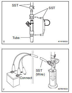
Connect sst (fuel tube connector) to sst (hose), then connect them to the fuel pipe (vehicle side).
Caution:Install a suitable vinyl tube onto the injector to contain gasoline spray.
Operate the fuel pump.
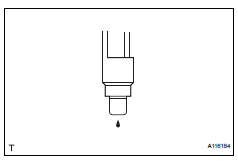
Connect sst (wire) to the injector and the battery for 15 seconds, and measure the injection volume with the graduated cylinder.
Test each injector 2 or 3 times. Sst 09842-30080Standard injection volume: 76 to 92 cm3 (4.6 To 5.6 Cu in.) Per 15 secondsStandard difference between each injector: 16 cm3 (1.0 Cu in.) Or less
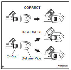
Inspect the fuel leakage.
Disconnect the sst (wire) tester probes from the battery and check the fuel leakage from the injector.
Standard fuel drop: 1 drop or less per 12 minutes
Turn the ignition switch off.
Disconnect the cable from the negative (-) battery terminal.
Remove sst.
Sst 09842-30080
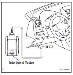
Disconnect the intelligent tester from the dlc3.
Reconnect the fuel inlet hose (rear fuel pipe) to the fuel main tube.
Installation
Install fuel injector assembly
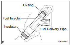
Apply a light coat of gasoline or spindle oil to new orings, then install one onto each fuel injector.
Apply a light coat of gasoline or spindle oil to the part of the fuel delivery pipe which comes into contact with the o-ring of the fuel injector.
Apply a light coat of gasoline or spindle oil to the oring again, then install the right and left fuel injectors onto the fuel delivery pipe.
Notice:
Make sure that the o-ring is not cracked or jammed when installing.
Check that the fuel injector rotates smoothly. If the fuel injector does not rotate, replace the o-ring.
Install fuel delivery pipe sub-assembly
Install 4 new insulators into the cylinder head.
Install the 2 delivery pipe spacers onto the cylinder head.
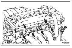
Install the fuel delivery pipe together with the 4 fuel injectors, then temporarily tighten the 2 bolts.
Notice:
Be careful not to drop the fuel injectors when installing the fuel delivery pipe.
Check that the fuel injector rotates smoothly.
If the fuel injector does not rotate, replace the oring.
Tighten the 2 bolts to the specified torque.
Torque: 20 n*m (205 kgf*cm, 15 ft.*Lb
f)
Connect the 4 fuel injector connectors.
Install the 2 wire harness clamps.
Connect no. 2 Ventilation hose
Connect the ventilation hose to the ventilation valve.
Notice:
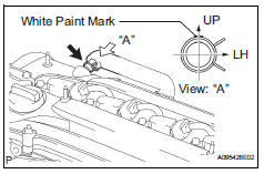
Make sure that the paint mark and hose clamp are at the correct angle when installing the hose.
Connect fuel main tube
Connect the fuel main tube.
Push the fuel tube connector until it makes a "click" sound.
Install the fuel pipe clamp.
Install the fuel tube to the fuel hose clamp.
Install air cleaner cap sub-assembly (see page es-413)
Install no. 1 Engine cover (see page es-414)
Connect cable to battery negative terminal
Check for fuel leakage
Make sure that there are no fuel leaks after performing maintenance on the fuel system.
Connect the intelligent tester to the dlc3.
Turn the ignition switch on, and push the intelligent tester main switch on.
Notice:
Do not start the engine.
Select the active test mode on the intelligent tester.
Hint:
Refer to the intelligent tester operator's manual for further details.
Check that there are no leaks from the fuel system.
Turn the ignition switch off.
Disconnect the intelligent tester from the dlc3.
?
Test yourself
A quick Toyota RAV4 quiz: every answer comes with an explanation and a link to the manual page.