2Az-fe engine mechanical
Removal
In this manual: 2Az-fe engine mechanical
71steps
~426min
4/5difficulty
Done 0 of 71
- Discharge fuel system pressure (see page fu-9)
- Disconnect cable from negative battery terminal
- Remove radiator support opening cover
- Remove front wheel rh
- Remove no. 1 Engine under cover
- Remove front fender apron rh
- Remove no. 1 Engine cover (see page em-22)
- Drain engine coolant (see page co-6)
- Drain engine oil (see page lu-4)
- Remove air cleaner cap (see page es-411)
- Remove throttle body (see page es-412)
- Remove fuel delivery pipe sub-assembly (see page fu-10)
- Remove intake manifold (see page es-419)
- Remove intake manifold insulator (see page es-420)
- Remove front exhaust pipe (see page ex-3)
- Remove oil dipstick
- Remove oil dipstick guide
- Remove the bolt and guide.
- Remove the o-ring from the guide.
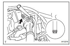
- Remove no. 2 Manifold stay
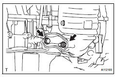
- Remove the bolt, nut and stay.
- Remove no. 1 Exhaust manifold heat insulator
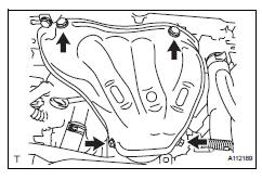
- Remove the 4 bolts and heat insulator.
- Remove exhaust manifold converter subassembly
- Disconnect the air-fuel ratio sensor connector.

- Remove the 5 nuts, manifold converter and gasket.

- Disconnect no. 1 Radiator hose
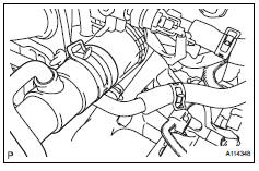
- Disconnect the no. 1 Radiator hose.
- Disconnect engine wire

- Disconnect the radio setting condenser connector.
- Disconnect the engine oil pressure switch connector.
- Disconnect the engine coolant temperature sensor connector.
- Disconnect the camshaft position sensor connector.
- Remove the bolt and ground cable.
- Remove front suspension member reinforcement rh (see page em-6)
- Remove fan and generator v belt (see page em-6)
- Remove generator assembly (see page ch-9)
- Remove engine mounting insulator rh (see page em-22)
- Remove idler pulley (see page em-23)
- Remove ignition coil assembly (see page ig-9)
- Remove spark plug (see page em-8)
- Remove cylinder head cover sub-assembly (see page em-24)
- Remove v-ribbed belt tensioner assembly (see page em-26)
- Remove crankshaft position sensor (see page es-402)
- Remove oil pan sub-assembly (see page em- 24)
- Set no. 1 Cylinder to tdc/compression

- Turn the crankshaft pulley until its groove and the timing mark "0" of the timing chain cover are aligned.
- Check that each timing mark of the camshaft timing gear and sprocket is aligned with each timing mark located on the no. 1 And no. 2 Bearing caps as shown in the illustration.
- Remove no. 2 Camshaft
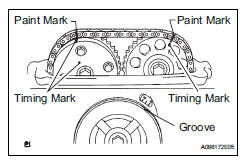
- Place paint marks on the chain in alignment with the timing marks on the camshaft timing gear and camshaft timing sprocket.
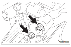
- Remove the 2 nuts, tensioner and gasket.
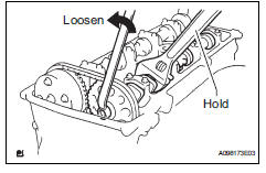
- While holding the camshaft with a wrench, loosen the camshaft timing set bolt.
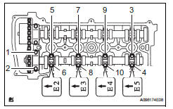
- Using several steps, uniformly loosen and remove the 10 bearing cap bolts in the sequence shown in the illustration.
- Remove the 5 bearing caps.
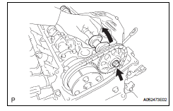
- While holding the no. 2 Camshaft by hand, remove the camshaft timing sprocket set bolt.
- Remove the camshaft timing sprocket from the no.
- Remove camshaft

- Using several steps, uniformly loosen and remove the 10 bearing cap bolts in the sequence shown in the illustration.
- Remove the 5 bearing caps.
- Remove the camshaft and camshaft timing gear while holding the timing chain by hand.
- Tie the timing chain with a string as shown in the illustration.
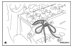
Notice:
Be careful not to drop anything inside the timing chain cover.
- Remove crankshaft pulley (see page em-25)
- Remove engine mounting bracket rh (see page em-26)
- Remove timing chain cover sub-assembly (see page em-26)
- Remove no. 1 Crankshaft position sensor plate
- Remove timing chain guide (see page em-28)
- Remove chain tensioner slipper (see page em-28)
- Remove no. 1 Chain vibration damper (see page em-28)
- Remove chain sub-assembly
- Remove camshaft timing oil control valve assembly (see page es-395)
- Remove camshaft timing gear assembly
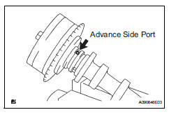
- Clamp the camshaft in a vise, and make sure that the camshaft timing gear does not rotate.
- Cover all the oil ports with vinyl tape except the advance side port shown in the illustration.
- Apply air pressure of 100 kpa (1.0 Kgf/cm2, 14 psi) to the oil path, then turn the camshaft timing gear to the advance direction (counterclockwise) by hand.
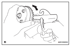
Caution: Cover the paths with a shop rag to avoid oil splashes. Hint:
Depending on the air pressure, the camshaft timing gear will turn to the advance angle side without applying force by hand. Also, under the condition that the pressure is difficult to apply because of air leakage from the port, there may be the case that the lock pin is difficult to release.
- Remove the flange bolt of the camshaft timing gear.
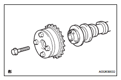
Notice:
- Be sure not to remove the other 4 bolts.
- When reusing the camshaft timing gear, release the straight pin lock first, then install the gear.
- Remove cylinder head sub-assembly
- Using several steps, uniformly loosen and remove the 10 cylinder head bolts and 10 plate washers with a 10 mm bi-hexagon wrench in the sequence shown in the illustration.
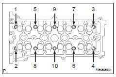
Notice:
Head warpage or cracking could result from removing the bolts in the wrong order.
- Using a screwdriver with its tip wrapped with tape, pry between the cylinder head and cylinder block, and remove the cylinder head.
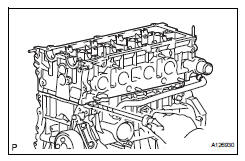
Notice:
Be careful not to damage the contact surfaces of the cylinder head and cylinder block.
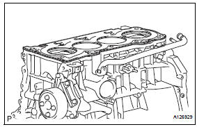
- Remove cylinder head gasket
Test yourself
A quick Toyota RAV4 quiz: every answer comes with an explanation and a link to the manual page.
Was this page helpful?