ECU Power Source Circuit
This circuit provides power for main body ECU (driver side junction block assembly) operation.
WIRING DIAGRAM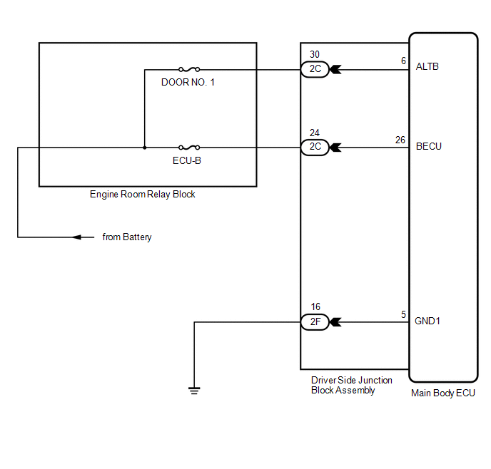
PROCEDURE
CHECK DRIVER SIDE JUNCTION BLOCK ASSEMBLY (MAIN BODY ECU (POWER SOURCE))
(a) Disconnect the 2C driver side junction block assembly connector. |
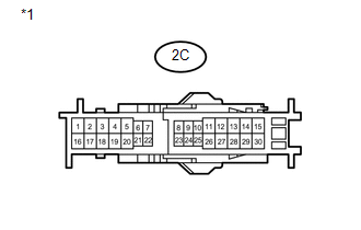 |
(b) Measure the voltage according to the value(s) in the table below.
Standard Voltage:
Tester Connection | Condition | Specified Condition |
|---|---|---|
2C-24 - Body ground |
Always |
11 to 14 V |
2C-30 - Body ground |
Always |
11 to 14 V |
*1 |
Front view of wire harness connector (to Driver Side Junction Block Assembly) |
| NG |  | REPAIR OR REPLACE HARNESS OR CONNECTOR |
|

CHECK HARNESS AND CONNECTOR (DRIVER SIDE JUNCTION BLOCK ASSEMBLY - BODY GROUND)
(a) Disconnect the 2F driver side junction block assembly connectors. |
 |
(b) Measure the resistance according to the value(s) in the table below.
Standard Resistance:
Tester Connection | Condition | Specified Condition |
|---|---|---|
2F-16 - Body ground |
Always |
Below 1 Ω |
*1 |
Front view of wire harness connector (to Driver Side Junction Block Assembly) |
| OK | | PROCEED TO NEXT SUSPECTED AREA SHOWN IN PROBLEM SYMPTOMS TABLE |
| NG | | REPAIR OR REPLACE HARNESS OR CONNECTOR |
Test yourself
A quick Toyota Venza quiz: every answer comes with an explanation and a link to the manual page.