Installation
1. INSTALL DISCHARGE HEADLIGHT BULB
HINT:
Use the same procedure for the RH side and LH side (See page  ).
2. INSTALL LIGHT CONTROL ECU (for LH Side)
(a) Turn the socket of the light control ECU in the direction indicated by the arrow shown in the illustration to connect it. Text in Illustration
NOTICE:
|
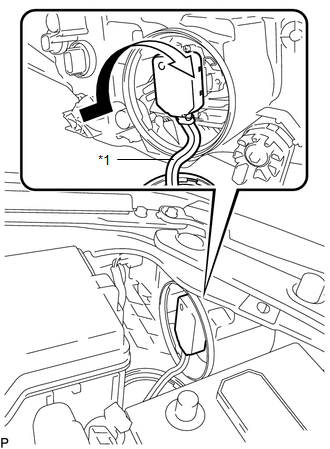 |
(b) Check that the red line on the output harness is not twisted and store the harness in the headlight assembly securely so that the output harness is not pinched.
(c) Turn the light control ECU in the direction indicated by the arrow shown in the illustration until the lock marks are aligned to install it. Text in Illustration
NOTICE:
|
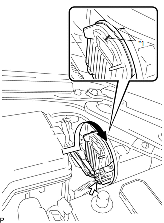 |
(d) Connect the connector.
3. INSTALL LIGHT CONTROL ECU (for RH Side)
(a) Turn the socket of the light control ECU in the direction indicated by the arrow shown in the illustration to connect it. Text in Illustration
NOTICE:
|
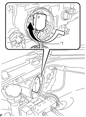 |
(b) Check that the red line on the output harness is not twisted and store the harness in the headlight assembly securely so that the output harness is not pinched.
(c) Turn the light control ECU in the direction indicated by the arrow shown in the illustration until the lock marks are aligned to install it. Text in Illustration
NOTICE:
|
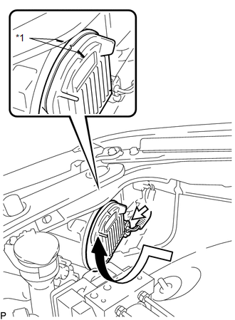 |
(d) Connect the connector.
4. INSTALL RADIATOR RESERVE TANK ASSEMBLY (for RH Side)
5. CONNECT CABLE TO NEGATIVE BATTERY TERMINAL
NOTICE:
When disconnecting the cable, some systems need to be initialized after the cable is reconnected (See page ).
Test yourself
A quick Toyota Venza quiz: every answer comes with an explanation and a link to the manual page.