Terminals Of Ecu
1. CHECK COMBINATION METER ASSEMBLY
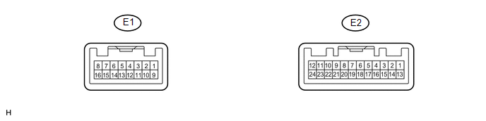
(a) Measure the resistance and voltage according to the value(s) in the table below.
Tester Connection | Wiring Color | Terminal Description | Condition | Specified Condition |
|---|---|---|---|---|
E2-14 (B) - Body ground |
Y - Body ground |
Battery power supply |
Always |
11 to 14 V |
E2-13 (IG+) - Body ground |
BR - Body ground |
Ignition switch power supply |
Ignition switch ON |
11 to 14 V |
E2-13 (IG+) - Body ground |
BR - Body ground |
Ignition switch power supply |
Ignition switch off |
Below 1 V |
E2-11 (E1) - Body ground |
B - Body ground |
Ground |
Always |
Below 1 Ω |
E2-24 (ES) - Body ground |
W - Body ground |
Ground |
Always |
Below 1 Ω |
E1-1 (CANH) - Body ground |
LG - Body ground |
CAN communication line |
Always |
200 Ω or higher |
E1-9 (CANL) - Body ground |
W - Body ground |
CAN communication line |
Always |
200 Ω or higher |
E1-5 (P/SB) - Body ground |
G - Body ground |
Front passenger side seat belt warning light signal |
Front passenger side seat occupied, seat belt fastened |
11 to 14 V |
E1-5 (P/SB) - Body ground |
G - Body ground |
Front passenger side seat belt warning light signal |
Front passenger side seat occupied, seat belt unfastened |
Below 1 V |
- If the result is not as specified, the combination meter assembly may have a malfunction.
2. CHECK ACCESSORY METER ASSEMBLY

(a) Measure the resistance and voltage according to the value(s) in the table below.
Tester Connection | Wiring Color | Terminal Description | Condition | Specified Condition |
|---|---|---|---|---|
F2-1 (B) - Body ground |
P - Body ground |
Battery power supply |
Always |
11 to 14 V |
F2-13 (IG+) - Body ground |
L - Body ground |
Ignition switch power supply |
Ignition switch ON |
11 to 14 V |
F2-13 (IG+) - Body ground |
L - Body ground |
Ignition switch power supply |
Ignition switch off |
Below 1 V |
F2-12 (E) - Body ground |
B - Body ground |
Ground |
Always |
Below 1 Ω |
F2-20 (PBEW) - Body ground |
G - Body ground |
Front passenger side seat belt warning light signal |
Front passenger side seat occupied, seat belt fastened |
11 to 14 V |
F2-20 (PBEW) - Body ground |
G - Body ground |
Front passenger side seat belt warning light signal |
Front passenger side seat occupied, seat belt unfastened |
Below 1 V |
- If the result is not as specified, the accessory meter assembly may have a malfunction.
3. CHECK CENTER AIRBAG SENSOR ASSEMBLY
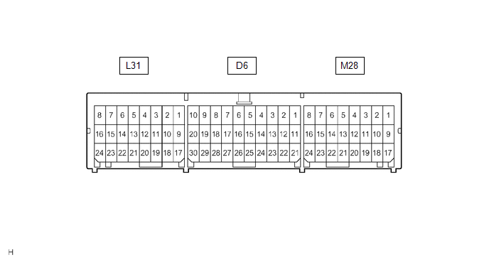
Terminal No. | Terminal Symbol | Destination |
|---|---|---|
M28-16 |
FSR+ |
Occupant classification ECU |
M28-24 |
FSR- |
Occupant classification ECU |
L31-10 |
LBE+ |
Front seat inner belt assembly (for driver side) |
L31-18 |
LBE- |
Front seat inner belt assembly (for driver side) |
4. CHECK OCCUPANT CLASSIFICATION ECU
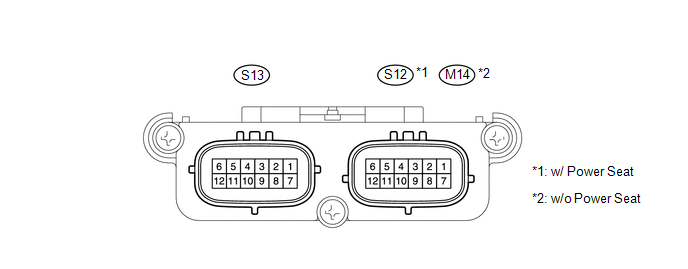
(a) Measure the voltage according to the value(s) in the table below.
Tester Connection | Wiring Color | Terminal Description | Condition | Specification |
|---|---|---|---|---|
S12-1 (+B) - S12-3 (GND)*1 M14-1 (+B) - M14-3 (GND)*2 |
GR - W-B*1 G - W-B*2 |
Battery power supply |
Always |
10 to 14 V |
S12-2 (DIA) - S12-3 (GND)*1 M14-2 (DIA) - M14-3 (GND)*2 |
SB - W-B |
Diagnosis (DLC3) |
Ignition switch ON |
Pulse generation |
S12-3 (GND) - Body ground*1 M14-3 (GND) - Body ground*2 |
W-B - Body ground |
Ground |
Always |
Below 1 V |
S12-7 (IG) - S12-3 (GND)*1 M14-7 (IG) - M14-3 (GND)*2 |
V - W-B |
Ignition switch power supply |
Ignition switch ON |
10 to 14 V |
S12-8 (FSR+) - S12-4 (FSR-)*1 M14-8 (FSR+) - M14-4 (FSR-)*2 |
W - B |
Center airbag sensor assembly communication line |
Ignition switch ON |
Pulse generation |
S12-9 (BSW) - S12-5 (BGND)*1 M14-9 (BSW) - M14-5 (BGND)*2 |
L - GR*1 G - Y*2 |
Front passenger side buckle switch line |
Always |
4 to 14 V |
S13-1 (SGD1) - S12-3 (GND)*1 S13-1 (SGD1) - M14-3 (GND)*2 |
R - W-B*1 Y - W-B*2 |
Front occupant classification sensor LH ground line |
Always |
Below 1 V |
S13-2 (SGD2) - S12-3 (GND)*1 S13-2 (SGD2) - M14-3 (GND)*2 |
Y - W-B*1 SB - W-B*2 |
Front occupant classification sensor RH ground line |
Always |
Below 1 V |
S13-3 (SGD3) - S12-3 (GND)*1 S13-3 (SGD3) - M14-3 (GND)*2 |
BR - W-B*1 L - W-B*2 |
Rear occupant classification sensor LH ground line |
Always |
Below 1 V |
S13-4 (SGD4) - S12-3 (GND)*1 S13-4 (SGD4) - M14-3 (GND)*2 |
LG - W-B*1 W - W-B*2 |
Rear occupant classification sensor RH ground line |
Always |
Below 1 V |
S13-11 (SVC1) - S13-1 (SGD1) |
Y - R*1 P - Y*2 |
Front occupant classification sensor LH power supply line |
Ignition switch ON, a load applied to front occupant classification sensor LH |
4.9 to 5.1 V |
S13-12 (SVC2) - S13-2 (SGD2) |
V - Y*1 BR - SB*2 |
Front occupant classification sensor RH power supply line |
Ignition switch ON, a load applied to front occupant classification sensor RH |
4.9 to 5.1 V |
S13-5 (SVC3) - S13-3 (SGD3) |
G - BR*1 R - L*2 |
Rear occupant classification sensor LH power supply line |
Ignition switch ON, a load applied to rear occupant classification sensor LH |
4.9 to 5.1 V |
S13-6 (SVC4) - S13-4 (SGD4) |
GR - LG*1 B - W*2 |
Rear occupant classification sensor RH power supply line |
Ignition switch ON, a load applied to rear occupant classification sensor RH |
4.9 to 5.1 V |
S13-7 (SIG1) - S13-1 (SGD1) |
P - R*1 BE - Y*2 |
Front occupant classification sensor LH signal line |
Ignition switch ON, a load applied to front occupant classification sensor LH |
0 to 5.1 V |
S13-8 (SIG2) - S13-2 (SGD2) |
GR - Y*1 GR - SB*2 |
Front occupant classification sensor RH signal line |
Ignition switch ON, a load applied to front occupant classification sensor RH |
0 to 5.1 V |
S13-9 (SIG3) - S13-3 (SGD3) |
L - BR*1 G - L*2 |
Rear occupant classification sensor LH signal line |
Ignition switch ON, a load applied to rear occupant classification sensor LH |
0 to 5.1 V |
S13-10 (SIG4) - S13-4 (SGD4) |
SB - LG*1 V - W*2 |
Rear occupant classification sensor RH signal line |
Ignition switch ON, a load applied to rear occupant classification sensor RH |
0 to 5.1 V |
- *1: w/ Power Seat
- *2: w/o Power Seat
- If the result is not as specified, the occupant detection ECU may have a malfunction.
Test yourself
A quick Toyota Venza quiz: every answer comes with an explanation and a link to the manual page.