Clutch Release Mechanism (Gearbox Type 084)
PROCEDURE

Clutch release mechanism: a – gearbox type 084 1 – clutch housing; 2 – guide sleeve; 3 – bolt; 4 – release bearing; 5 – retaining bracket; 6 – retaining spring; 7 – small bushing; 8 – clutch release lever shaft; 9 – large bushing; 10 – spring; 11 – retaining ring; 12 – release bearing lever; 13 – inner bushing; 14 – outer bushing; 15 – O-ring; A – projection; B – groove
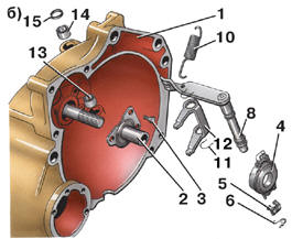
Clutch release mechanism: b – gearbox type 085 1 – clutch housing; 2 – guide sleeve; 3 – bolt; 4 – release bearing; 5 – retaining bracket; 6 – retaining spring; 7 – small bushing; 8 – clutch release lever shaft; 9 – large bushing; 10 – spring; 11 – retaining ring; 12 – release bearing lever; 13 – inner bushing; 14 – outer bushing; 15 – O-ring; A – projection; B – groove
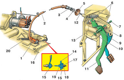
Clutch release linkage (gearbox type 084) 1 – clutch release lever; 2 – clutch cable sheath; 3 – end fitting; 4 – toothed washer; 5 – O-ring; 6 – pedal travel stop; 7 – clutch pedal shaft; 8 – bushing; 9 – clutch pedal tube; 10 – retaining ring; 11 – clutch pedal; 12 – clutch cable; 13 – dash panel cover; 14 – bracket; 15 – bushing; 16 – gearbox housing; 17 – lock nut; 18 – adjusting nut; 19 – threaded cable end; 20 – return spring
Removal PROCEDURE 1. Remove the gearbox (see sub-section 5.1). 2. Remove return spring 20 (see Clutch release linkage (gearbox type 084)) from lever 1. 3. Turn release lever shaft 8 (see Clutch release mechanism: a – gearbox type 084) in clutch housing 1 so that release bearing 4 moves up guide sleeve 2. 4. Remove the two retaining springs 6. 5. Remove release bearing 4. 6. Remove retaining brackets 5 from release bearing 4. 7. Unscrew bolts 3 and remove guide sleeve 2. On vehicles with gearbox type 084 8. Press out large bushing 9. 9. Remove release lever shaft 8. 10. Press out small bushing 7 (if replacement is required). On vehicles with gearbox type 085 Caution The release lever for gearbox type 085 has a different design. 11. Remove retaining rings 11 (see Clutch release mechanism: b – gearbox type 085). 12. Remove release lever shaft 8 from clutch housing 1, removing release bearing lever 12 and O-ring 15 at the same time. 13. Press out inner bushing 13 and outer bushing 14 (if replacement is required). Installation Caution Do not wash the release bearing, to avoid washing out its grease.
PROCEDURE 1. Install the clutch release mechanism in the reverse order of removal, observing the following. 2. Check the release bearing by rotating it. If the bearing binds, makes noise or has play between the races, replace it. 3. Check all bushings for wear. 4. Apply graphite grease to the surface of release bearing 4 and guide sleeve 2. 5. Press bushing 7 into clutch housing 1 flush with its seat. 6. Align projection A on bushing 9 with groove B in the clutch housing 1 bushing when pressing in bushing 9. 7. Press inner bushing 13 and outer bushing 14 flush with their seats in clutch housing 1 (gearbox type 085).
Test yourself
A quick Volkswagen Golf quiz: every answer comes with an explanation and a link to the manual page.