Camshaft Drive
PROCEDURE
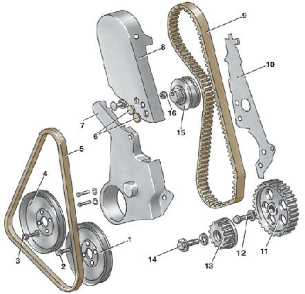
Camshaft Drive Components 1 – water pump pulley; 2 – water pump pulley bolt; 3 – crankshaft pulley bolt; 4 – crankshaft pulley; 5 – alternator drive belt; 6 – plugs; 7 – lower camshaft drive cover; 8 – upper camshaft drive cover; 9 – camshaft drive belt; 10 – rear camshaft drive cover; 11 – intermediate shaft gear; 12 – intermediate shaft gear bolt; 13 – crankshaft gear; 14 – crankshaft gear bolt; 15 – camshaft drive belt tensioner; 16 – tensioner nut
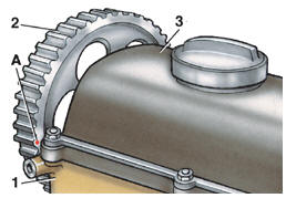
Position of the Camshaft Gear Timing Mark with No. 1 Piston at TDC 1 – cylinder head; 2 – camshaft gear; 3 – cylinder head cover; A – TDC mark on camshaft gear
Disassembly. PROCEDURE 1. Loosen the alternator adjusting bar bolts at the cylinder head and the alternator bolts at the bracket and at the adjusting bar. Pivot the alternator toward the engine to relieve belt tension 5 (see Camshaft Drive Components) and remove the alternator belt. 2. Remove the four bolts 2 and remove water pump pulley 1. 3. Remove upper camshaft drive cover 8. 4. Disconnect the crankcase ventilation hose from the cylinder head cover. 5. Remove the cylinder head cover together with its gasket and hold-down plates. 6. Remove the four bolts 3 and remove crankshaft pulley 4. 7. Remove lower camshaft drive cover 7. 8. Loosen the camshaft, crankshaft and intermediate shaft gear bolts.
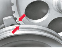
9. Set No. 1 piston to TDC on the compression stroke. To do this, temporarily install the crankshaft pulley, secured with one bolt. Turn the crankshaft so that the mark on the crankshaft pulley aligns with the mark on the intermediate shaft gear, as shown in the illustration.
In this position, the mark on the camshaft gear must align with the upper edge of the cylinder head cover, as shown in the illustration Position of the Camshaft Gear Timing Mark with No. 1 Piston at TDC. Both valves of cylinder No. 1, counting from the camshaft drive belt, are closed and the camshaft cams point upward. Remove the crankshaft pulley. 10. Loosen nut 16 and turn tensioner 15 counterclockwise with a wrench to release belt tension 9.
11. Remove belt 9 from the camshaft, crankshaft 13 and intermediate shaft 11 gears and from the tensioner pulley 15. 12. Remove nut 16 and remove tensioner 15. 13. Remove bolt 12 and remove intermediate shaft gear 11, remove the key. 14. Remove bolt 14 and remove crankshaft gear 13, remove the key. 15. Remove the bolt and remove the intermediate shaft gear, remove the key. 16. Remove the bolts and remove rear camshaft drive cover 10. Installation

Adjustment and Checking of Camshaft Drive Belt Tension 1 – camshaft drive belt tensioner; 2, 3 – wrenches; 4 – camshaft gear; 5 – camshaft drive belt; 6 – intermediate shaft gear
PROCEDURE 1. Install rear camshaft drive cover 10 (see Camshaft Drive Components) and tighten its bolts. 2. Insert the key into the keyway on the crankshaft and install gear 13.
Apply thread locking compound "D6" to the threads of bolt 14, install the bolt with washer and tighten to 200 N·m (on vehicles built from March 1988, a twelve-point head bolt is installed, tightening torque 90 N·m). 3. Insert the key into the keyway on the camshaft, install the gear, install the bolt with washer and tighten to 80 N·m. The mark on the camshaft gear must align with the upper surface of the cylinder head cover (see illustration Position of the Camshaft Gear Timing Mark with No. 1 Piston at TDC).
If the camshaft must be turned, first rotate the crankshaft approximately 90° so that no piston is at TDC.
4. Insert the key into the keyway on the intermediate shaft, install gear 11, install bolt 12 with washer and tighten to 80 N·m. 5. Install tensioner 15, install nut 16 but do not tighten it.
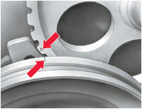
6. Temporarily install crankshaft pulley 4 on gear 13. The mark on pulley 4 must align with the mark on gear 11. 7. Install belt 9 on the camshaft, crankshaft and intermediate shaft gears and on the tensioner pulley. Make sure the TDC marks have not moved.
8. Tension the belt. 9. To do this, turn tensioner 1 clockwise with wrench 3 (see figure Adjusting and Checking Camshaft Drive Belt Tension) to preliminarily tension the belt. Make sure the TDC marks have not shifted. Turn tensioner 1 further clockwise, tensioning belt 5 so that it can be twisted no more than 90° by grasping it with two fingers at the midpoint between the camshaft and intermediate shafts.
While holding tensioner 1 in this position with wrench 3, tighten the tensioner mounting nut with wrench 2. Turn the crankshaft two revolutions and check that the TDC marks align. Remove pulley 4 (see figure Camshaft Drive Components). 9. Install lower camshaft drive cover 7. 10. Install pulley 4, install bolts 3 and tighten to 20 N·m torque. 11. Install camshaft drive cover 8. 12. Install water pump pulley 1, install bolts 2 and tighten them to 20 N·m torque. 13. Install belt 5. 14. Tension belt 5 by levering the alternator away from the cylinder block so that it deflects 5 mm (2 mm for a new belt) when pressed with a finger at the midpoint between the alternator and crankshaft pulleys. Tighten the alternator mounting bolt to the adjusting bracket, then the alternator mounting bolt to the bracket.
Test yourself
A quick Volkswagen Golf quiz: every answer comes with an explanation and a link to the manual page.