Heating, air conditioning

Removing and installing heater and air conditioning unit

~4min read
0204060801005037N·mlb·ft
Tightening torque found on this page

Special tools and workshop equipment required

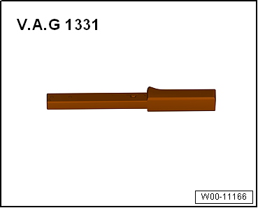
Torque wrench -V.A.G 1331/- (5…50 N·m)

Removing and installing heater and air conditioning unit

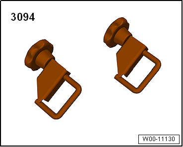
Hose clamps up to 25 mm -3094-

Removing and installing heater and air conditioning unit

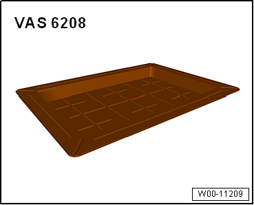
Drip tray for workshop hoist -VAS 6208-

Removing and installing heater and air conditioning unit

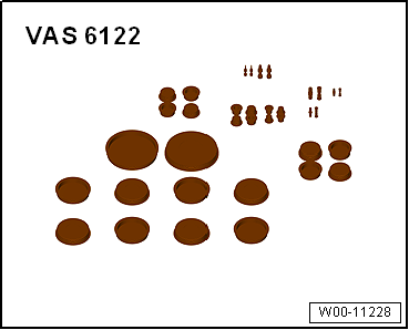
Engine bung set -VAS 6122-

Air conditioner service station

Commercially available compressed-air gun

Removing

Note Removal and installation for a left-hand drive vehicle is described; the procedure for a right-hand drive vehicle is analogous. Depending on engine version, additional components, e.g. the engine cover panel or the air filter housing, must be removed to improve access → Rep. gr.10 or → Rep. gr.23.
  • Heed the safety precautions → Chapter „Safety instructions“.
  • Vehicles with air conditioning system: extract refrigerant, e.g. with air conditioner service station. Only then open refrigerant circuit. Comply with notes → Chapter.
  • Vehicles with air conditioning system: Disconnect refrigerant line with internal heat exchanger on expansion valve → Chapter.
Removing and installing heater and air conditioning unit
  • Place drip tray -VAS 6208- beneath engine.
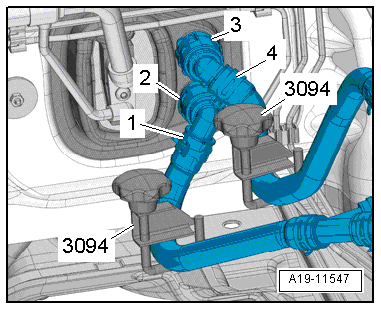
  • Mark coolant hoses -1- and -4-.
Note The heat exchanger is designed for a particular direction of flow of the coolant. Therefore, the coolant hoses must not be interchanged when connecting them.
  • Clamp off coolant hoses -1- and -4- using hose clamps, up to 25 mm -3094-.
When the engine is warm, the cooling system is under pressure. Danger of scalding due to steam and hot coolant. There is a risk of injury to the skin and parts of the body due to scalding.Always wear safety gloves.Always wear safety goggles.Proceed as follows to release the pressure: cover the cap of the coolant expansion tank with a cloth, and open it carefully.
Removing and installing heater and air conditioning unit
  • Lift retaining clips -2- and -3-.
  • Disconnect coolant hoses -1- and -4- from heat exchanger for heater.
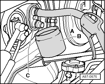
  • Push a piece of hose -A- onto upper union.
  • Insert compressed air gun into end of hose.
  • Hold drip tray -B- under connection -C- and carefully blow coolant out of heat exchanger using compressed air gun.
  • Seal off open lines and connections with clean plugs from engine bung set -VAS 6122-.
Note To seal open connections of expansion valve, use, for example, sealing cover from spare expansion valve.
  • Remove dash panel central tube → General body repairs, interior; Rep. gr.70.
  • Remove air duct leading to rear vent (depending on vehicle) → Chapter.
  • Lift rear footwell vents under front seats and pull them towards rear to ease removal of footwell vents from heater and air conditioning unit.
  • Remove rear footwell vents from heater and air conditioning unit.
Removing and installing heater and air conditioning unit
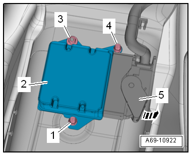
  • Disconnect connector -3- from fresh air blower control unit -J126-.
  • Pull connector -5- off airbag control unit -J234- (on tunnel) -2-.
Removing and installing heater and air conditioning unit
  • Cover floor covering and airbag control unit -J234- in interior of vehicle with impermeable sheeting and absorbent paper.
Removing and installing heater and air conditioning unit
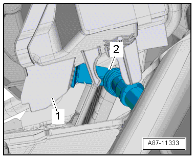
  • Carefully pull condensation drain hose -2- off heater and air conditioning unit -1-.
Removing and installing heater and air conditioning unit
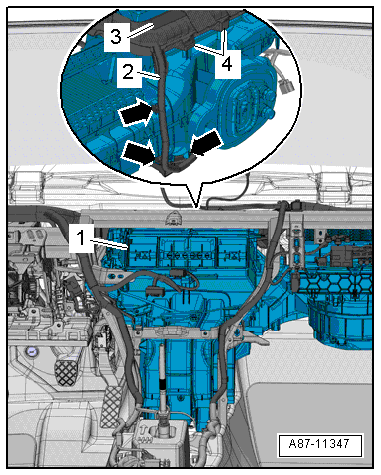
  • Pull heater and air conditioning unit -1- off retainers on plenum chamber bulkhead.
  • Lay bare the duct -3-.
  • Lay wiring harness -2- on mountings -4- to one side -arrows-.
  • Remove heater and air conditioning unit to the side.

Installing

Installation is carried out in the reverse order. When installing, note the following: Note The aid of a second mechanic is required to install the heater and air conditioner unit.
Removing and installing heater and air conditioning unit
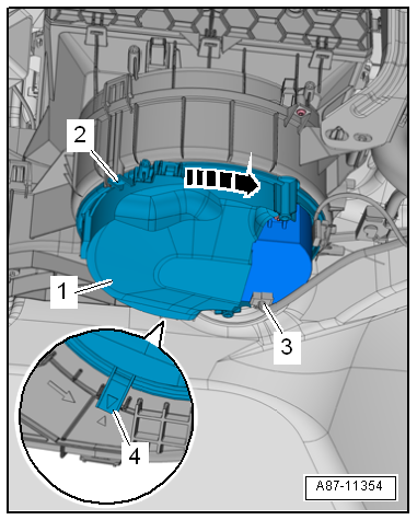
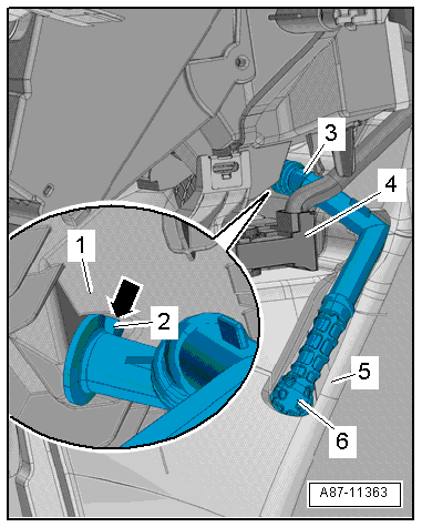
  • When installing, ensure that condensation drainage hose -3- is properly seated.
  • Lug -arrow- on connecting piece of heater and air conditioning unit -1- must engage in guide -2-.
  • If a commercially available cable tie was installed to retain the condensation drain -3-, then renew it.
  • The condensation drain hose must be routed below the wiring harness of the airbag control unit -J234--4- in the figure.
  • Fill with coolant → Rep. gr.19.
  • Refilling with refrigerant R134a and refrigerant oil → Chapter.
  • As a final step, check operation of the heater/air conditioner.

Specified torque

→ Chapter „Assembly overview - heater and air conditioning unit“

→ Chapter „System overview - refrigerant circuit“

Dash panel central tube; Assembly overview - dash panel central tube → General body repairs, interior; Rep. gr.70.

Engine cover panel → Rep. gr.10.

Air filter housing → Rep. gr.23.

Removing and installing heater and air conditioning unit

Test yourself

A quick Volkswagen Golf quiz: every answer comes with an explanation and a link to the manual page.