Steering Column Electronics Control Module -J527-
General Information
The Steering Column Electronics Control Module -J527- includes the following components and cannot be disassembled:
- Airbag Spiral Spring/Return Spring with Slip Ring -F138-
- Steering Angle Sensor -G85-
WARNING
Before working on electronic system and removing the steering wheel the following conditions must be met:
The technician must discharge static electricity. This is accomplished by touching grounded metal like, for example, water pipes, heating pipes, metal carriers or a heater pipe.
If this note is ignored it can result in failure of the control modules during later operation.
- Remove the battery ground cable.
- Wheels must be located in straight ahead position.
If this note is ignored, it can result in failure of the airbag system during later operation.
Note
- Remove the transportation safeguard before assembling if a new Steering Column Electronics Control Module -J527- is being installed.
- Code the new Steering Column Electronics Control Module -J527- after installing it.
- If the steering column switch malfunctions, the coding of the Steering Column Electronics Control Module -J527- must be checked.
Caution
If the universal joint is separated from the steering gear, or the Steering Angle Sensor -G85- is removed, do not perform the following tasks:
- Connecting the battery
- Turning on the ignition
- Turning the steering gear.
- Turning the steering column.
These points must be followed otherwise, it can lead to irreparable damage.
The procedure for removing and installing the Steering Column Electronics Control Module -J527- differs between manufacturers.
- Steering Column Electronics Control Module -J527-, Removing and Installing, Valeo.
- Steering Column Electronics Control Module -J527-, Removing and Installing, Kostal.
Steering Column Electronics Control Module -J527-, Removing and Installing, Valeo
Removing
Caution
Always follow the sequence when removing and installing steering column switch components.
WARNING
- Risk of airbag deployment.
- The airbag unit could deploy if mishandled.
- Follow the safety precautions when working on the airbag.
Caution
Always follow the procedure as described in the Repair Manual when disconnecting and connecting the battery.
WARNING
Before working on electronic system and removing the steering wheel the following conditions must be met:
The technician must discharge static electricity. This is accomplished by touching grounded metal like, for example, water pipes, heating pipes, metal carriers or a heater pipe.
If this note is ignored it can result in failure of the control modules during later operation.
- Remove the battery ground cable.
- Wheels must be located in straight ahead position.
If this note is ignored, it can result in failure of the airbag system during later operation.
Caution
If the universal joint is separated from the steering gear, or the Steering Angle Sensor -G85- is removed, do not perform the following tasks:
- Connecting the battery
- Turning on the ignition
- Turning the steering gear.
- Turning the steering column.
These points must be followed otherwise, it can lead to irreparable damage.
- Disconnect the battery.
Remove the following components in the correct order:
- Remove the steering wheel.
- Remove the steering column trim panel.
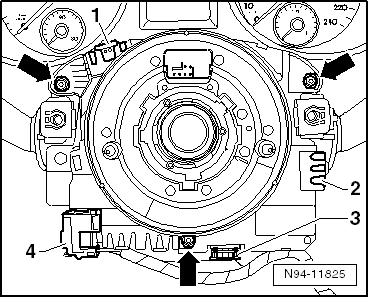
- Release and disconnect the equipment-dependent connectors -1-, -2-, -3- and -4-.
Note
Do not turn the spiral spring on the Steering Column Electronics Control Module -J527- from its center position during removal. The front wheels must be in the "straight-ahead position".
- Remove the three screws -arrows- and remove the Steering Column Electronics Control Module -J527- from the steering column switch toward the rear.
Installing
Install in reverse order of removal. Note the following:
Caution
The turn signal switch lever could break when installing the control module.
The turn signal lever must be in the 0 position when installing the spiral spring so that it does not fall out.
- Slide the Steering Column Electronics Control Module -J527- straight onto the steering column switch.
- Install the three screws for the Steering Column Electronics Control Module -J527- on the steering column switch and then tighten them to 1,5 N·m.
- Install all components accordingly in the reverse order.
Steering Column Electronics Control Module -J527-, Removing and Installing, Kostal
Removing
Caution
Always follow the sequence when removing and installing steering column switch components.
WARNING
- Risk of airbag deployment.
- The airbag unit could deploy if mishandled.
- Follow the safety precautions when working on the airbag.
Caution
Always follow the procedure as described in the Repair Manual when disconnecting and connecting the battery.
WARNING
Before working on electronic system and removing the steering wheel the following conditions must be met:
The technician must discharge static electricity. This is accomplished by touching grounded metal like, for example, water pipes, heating pipes, metal carriers or a heater pipe.
If this note is ignored it can result in failure of the control modules during later operation.
- Remove the battery ground cable.
- Wheels must be located in straight ahead position.
If this note is ignored, it can result in failure of the airbag system during later operation.
Caution
If the universal joint is separated from the steering gear, or the Steering Angle Sensor -G85- is removed, do not perform the following tasks:
- Connecting the battery
- Turning on the ignition
- Turning the steering gear.
- Turning the steering column.
These points must be followed otherwise, it can lead to irreparable damage.
- Disconnect the battery.
Remove the following components in the correct order:
- Remove the steering wheel.
- Remove the steering column trim panel.
- Release and disconnect the equipment-dependent connectors -1-, -2-, -3-, -4- and -5-.
- Remove the screw -arrow B-.

Note
Do not turn the spiral spring on the Steering Column Electronics Control Module -J527- for the steering column electronics from its center position during removal. The front wheels must be in the "straight-ahead position".
- Open both latching mechanisms -arrows A- and pull the Steering Column Electronics Control Module -J527- toward the back off of the steering column switch.
Installing
Install in reverse order of removal. Note the following:
Caution
The turn signal switch lever could break when installing the control module.
The turn signal lever must be in the 0 position when installing the spiral spring so that it does not fall out.
- Slide the Steering Column Electronics Control Module -J527- straight onto the steering column switch until it locks in place.
- Install the screw for the Steering Column Electronics Control Module -J527- on the steering column switch and then tighten them to 1,5 N·m.
- Install all components accordingly in the reverse order.
Steering Column Electronics Control Module -J527-, Coding
- Code the Steering Column Electronics Control Module -J527- using the Vehicle Diagnostic Tester.
Test yourself
A quick Volkswagen Tiguan quiz: every answer comes with an explanation and a link to the manual page.