Wheel alignment
Notes on wheel alignment
The vehicle may only be aligned with a wheel alignment system approved by VW/AUDI!
Both the front and rear axles must be measured during every alignment.
Otherwise the centre position of the steering rack cannot be guaranteed!
- Carry out the alignment using the wheel alignment computer.
All information required for a vehicle alignment can be found in the wheel alignment computer.
Current data "updates" are stored in VW ServiceNet.
→ VW Service Net; Systems; Wheel alignment software; Wheel alignment; Beissbarth
→ VW Service Net; Systems; Wheel alignment software; Wheel alignment; Hunter
→ VW Service Net; Systems; Wheel alignment software; Wheel alignment; Corghi
→ VW Service Net; Systems; Wheel alignment software; Wheel alignment; John Bean

Note
- It is advisable to carry out the wheel alignment only after 1000 to 2000 km of mileage, as the coil springs only finish settling after this.
- When making adjustments, aim for the specified nominal values as precisely as possible.
Need for wheel alignment
A wheel alignment is required if:
- There are driving behaviour faults.
- There is accident damage and components have been replaced.
- Axle parts have been removed or replaced.
- There is one-sided tyre wear.
Components replaced
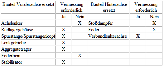
Components removed and installed
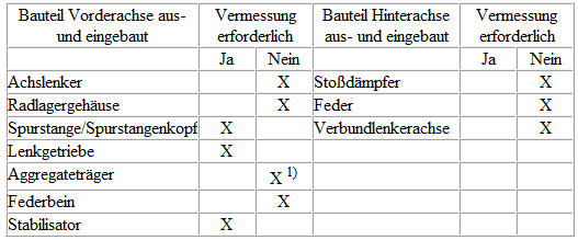
1) Prerequisite: The subframe was secured before removal.
Test prerequisites
- Wheel suspensions, wheel bearings, steering and steering linkage checked for impermissible play and damage.
- The tread depth on one axle may differ by a maximum of 2 mm.
- Tyres inflated to the specified tyre pressure.
- Kerb weight of the vehicle.
- Fuel tank must be full.
- Spare wheel and tool kit in the corresponding installation location in the vehicle.
- The washer fluid reservoir for the windshield washer system/headlight washer system must be full.
- Make sure that no sliding plates and no turntables are at the end stop during the measurement.
Note!
- Mount and adjust the measuring equipment as specified; observe the operating instructions of the equipment manufacturer!
If necessary, have the alignment rack/wheel alignment equipment manufacturer provide instruction.
The alignment rack and the wheel alignment equipment/alignment computer may deviate from their original leveling/calibration over time.
As part of maintenance, the alignment rack and the wheel alignment equipment/alignment computer should be checked at least once a year and adjusted if necessary!
- Handle these highly sensitive devices carefully and conscientiously!
Measurement preparation
Required Special Tools, Test and Measuring Equipment and Auxiliary Items
- Wheel alignment computer -V.A.G 1813F- or the wheel alignment equipment approved by VW/Audi
- Brake pedal depressor -V.A.G 1869/2-
- Shock absorber set -T10001-
Existing wheel runout must be compensated. Otherwise the measurement result will be falsified.
A correct toe setting is not possible without runout compensation!
Observe the instructions of the wheel alignment equipment manufacturer.
- Perform wheel runout compensation.
- Insert brake pedal loader -V.A.G 1869/2-.
- Depress the brake pedal with the brake pedal depressor.
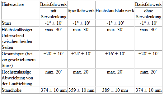
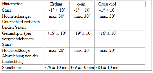
Wheel alignment specifications
These specifications apply to all engine variants.
- Explanations of the PR numbers can be found here.
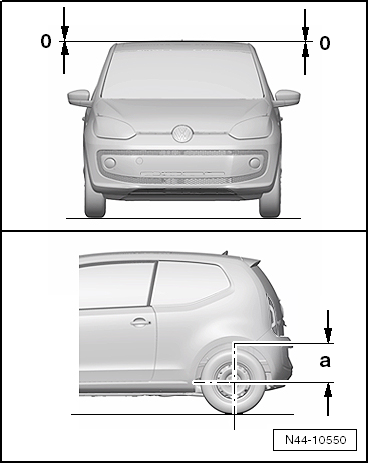
The ride heights given in the tables refer to dimension -a-.

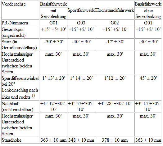
1) Depending on the manufacturer, the total toe angle may also be displayed as a negative value in the wheel alignment computer.
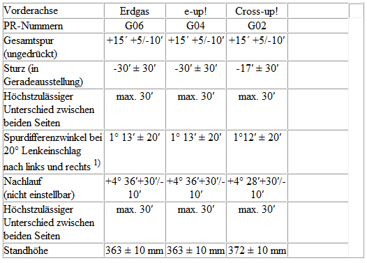
1) Depending on the manufacturer, the total toe angle may also be displayed as a negative value in the wheel alignment computer.
These specifications apply to all engine variants with the vehicle transverse tilt in the "zero position".
- Explanation of the "zero position" of the vehicle transverse tilt
- Explanations of the PR numbers can be found here
If the measured values are outside the tolerance of the specifications, the cause may be a vehicle that is standing crooked.
Right-hand drive vehicles or, for example, vehicles with automatic transmission may stand slightly crooked.
This is normal due to the installation position of the components and the resulting weight distribution.
- Then be sure to check dimension -a- on the left and right at the rear.
- If necessary, correct the existing difference.
At the front axle, you can compensate by placing weights on the respective strut dome in the engine compartment.
At the rear axle, you can compensate by placing weights in the luggage compartment on the respective side.
Sandbags (approx. 10 kg), for example, are suitable as weights.
Vehicle data plate
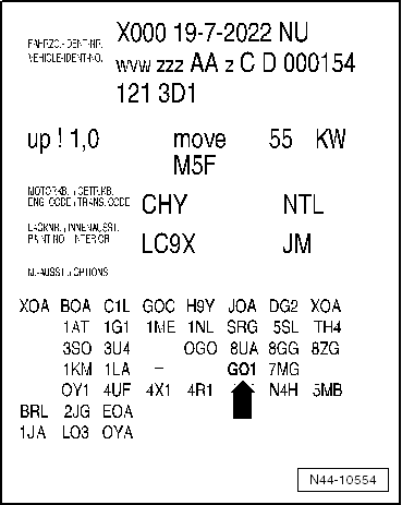
Explanations for the "PR no." on the vehicle data plate
Depending on the engine and equipment, different suspensions are installed. These are identified by PR numbers.
The PR numbers are decisive for assigning the specifications to the vehicle.
Which suspension is installed in the vehicle is documented on the vehicle data plate by the corresponding PR number for the front axle.
The vehicle data plate is located in the spare wheel well and in the service booklet.
Example of a vehicle data plate
In this example, the basic suspension G01 -arrow- is installed in the vehicle.
Overview of the workflow for wheel alignment
The following sequence of work steps must be observed!
- Observe the notes in the wheel alignment equipment.
Measurement procedure
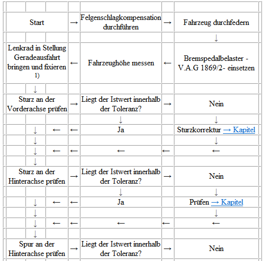
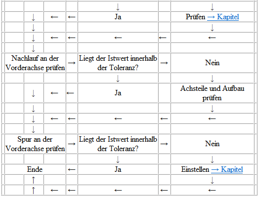
1) If the steering wheel is crooked, it must be straightened at the end of the wheel alignment. Then perform basic setting for the steering angle sensor -G85- with Vehicle Diagnostic, Measurement and Information System -VAS 5051-.
Adjusting camber at the front axle
Required Special Tools, Test and Measuring Equipment and Auxiliary Items
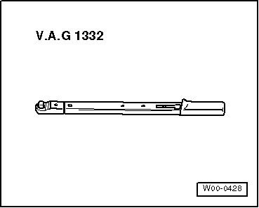
- Torque Wrench -V.A.G 1332-

Note
- Camber correction is only required after body repair. Camber is not adjustable. However, it can be corrected by shifting the subframe!
- Shift the subframe only to the left or right, never forward or backward in relation to the direction of travel!
- Remove the noise insulation.
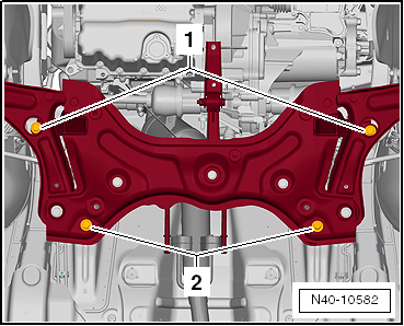
- Loosen bolts -1- and -2- securing the subframe to the body.
The camber adjustment range is limited by the tolerances in the holes of the subframe. If the specification cannot be reached by shifting the subframe, the subframe and the body must be checked.
- Shifting the subframe can now set the camber specification.
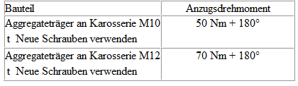
- Tighten the subframe to the body with new bolts using the additional turning angle.
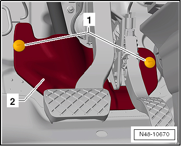
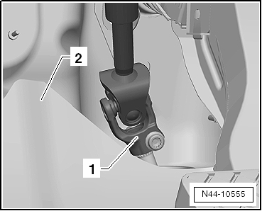
After shifting the subframe, check the clearance between the universal joint of the steering column and the cutout in the bulkhead.
- Unscrew bolts -1- and remove footwell trim -2-.
There must now be a clearance of at least 5 mm all around between universal joint -1- and the cutout in the bulkhead -2-.
Tightening torques
Adjusting camber at the rear axle
Camber cannot be adjusted.
If the values are outside the tolerance, first check the transverse tilt and correct it if necessary.
If the measured values are still outside the permissible tolerance, check the axle beam for damage and replace it if necessary.
Adjusting toe at the rear axle
Toe cannot be adjusted.
If the values are outside the tolerance, first check the transverse tilt and correct it if necessary.
If the measured values are still outside the permissible tolerance, check the axle beam for damage and replace it if necessary.
Adjusting toe at the front axle
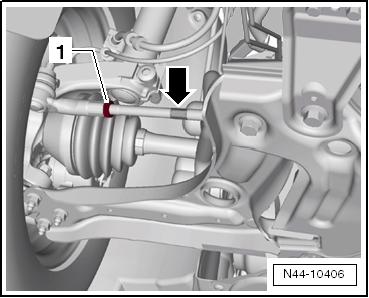
- Loosen lock nut -1-.
- Adjust toe by turning the left and/or right tie rod.
To do so, place an open-end wrench on the hex -arrow- of the tie rod.
Make sure the bellows are not twisted after turning the tie rods!
Twisted bellows wear out quickly.
- Tighten lock nut -1-.
- Check the toe value again.
After tightening lock nut -1-, the set value may deviate slightly.
However, if the measured toe value is within the tolerance, the adjustment is correct.
Tightening torques

Checking maximum steering angle
This check is only required if:
- the steering stops, measured from the steering center, differ by more than 2º,
- at full steering lock, the tire contacts components of the front axle or the body on one side,
- the turning circle differs between left and right.
The distance between the control arm and the tire (arrows) must be equal at maximum steering lock.
If the distance is uneven, correct it by turning the left and right tie rods.
Example:
The steering lock to the left is smaller than to the right.
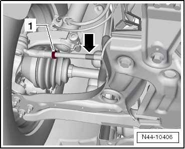
- Loosen the tie rod lock nuts.
- Turn the left tie rod (unscrew it from the tie rod end).
- Turn the right tie rod by the same amount in the opposite direction (screw it into the tie rod end).
- Check the total toe.
After this adjustment, the total toe must match the specified nominal value!
- Tighten the lock nuts.

After tightening lock nut -1-, the set value may deviate slightly.
If the adjustment value deviates from the nominal value by no more than 2′, the adjustment is acceptable.
Make sure the bellows are not twisted after turning the tie rods!
Tightening torques
