Passenger airbag
Assembly overview - Passenger airbag
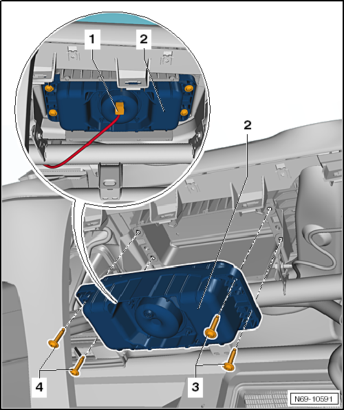
- Electrical connector
- for igniter 1 for passenger airbag -N131-
- Passenger airbag with igniter 1 for passenger airbag -N131-

WARNING!
- Observe the safety regulations for pyrotechnic components.
- Note the assignment of the airbag unit to the instrument panel → Electronic parts catalog.
- Bolt
- 2 pieces
- Replace
- Install with locking agent D 154 000 A1.
- 8 N·m
- Bolt
- 2 pieces
- Replace
- Install with locking agent D 154 000 A1.
- 8 N·m
Removing and installing passenger airbag unit with igniter
Removing

WARNING!
- Observe the safety regulations for pyrotechnic components.
- Observe the disposal regulations for pyrotechnic components.
- Note the assignment of the airbag unit to the instrument panel → Electronic parts catalog.
- On e-up! vehicles, disconnect service plug for high-voltage system -TW-.
- Disconnect the battery ground cable with ignition switched on → Electrical system.
- Remove glove box.

WARNING!
Before handling pyrotechnic components (for example, disconnecting the electrical connector), the person handling them must "discharge static electricity". To do this, briefly touch the door striker plate, for example.
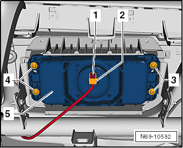
- Carefully pull out the connector lock -1- with a small screwdriver -arrow- and disconnect the electrical connector -2-.
- Unscrew the 2 bolts -3- and -4- respectively.
- Remove the passenger airbag downward.

WARNING!
Place the airbag down so that the airbag cushion faces up.
Installing

WARNING!
- Observe the safety regulations for pyrotechnic components.
- Before handling pyrotechnic components (for example, connecting the electrical connector), the person handling them must "discharge static electricity". For example, briefly touch the door striker.
- Note the assignment of the airbag to the instrument panel → Electronic parts catalog.
Installation is carried out in the reverse order, observing the following:

Note
- Make sure that the electrical connectors are pushed on as far as they will go and audibly engage.
- Make sure that the wiring is not pinched.
- After an airbag deployment, replace the instrument panel.

WARNING!
The battery must be connected with the ignition switched on. Improper repair work on pyrotechnic components (for example airbags or belt tensioners) can cause unintended deployment after the battery is connected. No person may be inside the vehicle cabin when connecting the battery.
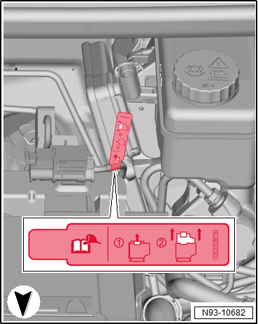
- On e-up! vehicles, connect the service plug for high-voltage system -TW-.
- Connect the battery ground cable with ignition switched on → Electrical system.

Note
If the airbag warning lamp -K75- signals a fault after installation, the fault memory must be read out, cleared and read out again → Vehicle diagnostic tester.
Installation notes: e.g. tightening torques, replacing components
Removing and installing key switch for passenger airbag deactivation
Removing
- On the passenger side, remove the side cover of the instrument panel.
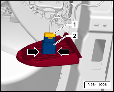
- Unlock connector -1- and disconnect it.
- Press the latches -arrows- on both sides and push the key switch for passenger airbag deactivation -E224- -2- through the cover.
Installing
Installation is carried out in the reverse order, observing the following:

Note
- Make sure that the electrical connectors are pushed on as far as they will go and audibly engage.
- Make sure that the wiring is not pinched.
- Make sure that the key switch for passenger airbag deactivation -E224- audibly engages in the cover.
Installation notes: e.g. tightening torques, replacing components
Removing and installing passenger airbag OFF indicator lamp
The passenger airbag OFF indicator lamp -K145- is integrated in the right switch module of the center instrument panel and can only be replaced together with the hazard warning light switch -E229- and the rear window heating switch -E230-.
Removing
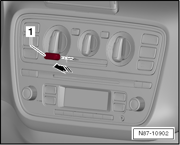
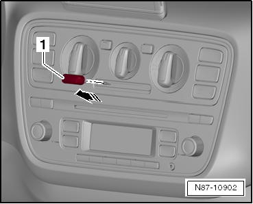
- Remove slide control for fresh air and recirculation mode -1- in direction of arrow.
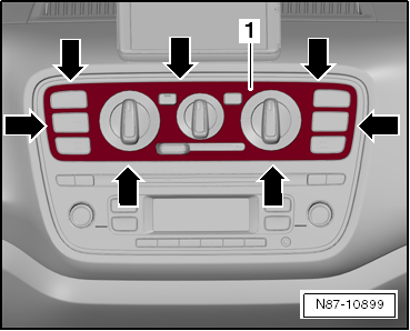
- Unclip cover -1- at the relevant points -arrows- using removal wedge -3409- and remove cover -1-.
- Remove the right switch module of the center instrument panel → Electrical system.
Installing
Installation is carried out in the reverse order, observing the following:

Note
Always install slider for fresh air and recirculation mode -1- with the plug base facing up.