Radio / radio navigation systems
Radio / radio navigation system design
"RCD 215" radio system
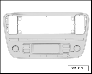
"RCD 215" radio view
The "RCD 215" radio system consists of the radio and the loudspeakers. For further information, refer to the Sound system chapter
- "RCD 215" features
- Anti-theft coding

Note
- When complaints are received, it is essential to know the function and operation of the radio.
- Additional information → Owner's manual
- The anti-theft coding is equipped with a fixed code
- When carrying out repair work or fault finding, use the vehicle diagnostic tester in the "Guided fault finding" or "Guided functions" function.
- → Wiring diagrams, electrical fault finding and installation locations.
- When reconnecting the battery, remember to check the vehicle equipment (radio, clock, comfort electrics, etc.) in accordance with the repair manual and/or the owner's manual.
"RCD 215" features
The "RCD 215" radio has the following device features:
- Display: monochrome
- Single FM tuner
- CD drive
- UHV-Low (mono input)
- MP3 with ID3 tag
- FM/AM European radio
- 2 or 4 x 20 watt output power
- AUX-IN connection
- external CD changer connection without MP3
- Multifunction steering wheel (MFL) support
- speed-dependent volume control (GALA)
- Self-diagnosis including loudspeaker diagnosis
- CAN, TP 2.0
- Comfort coding
The CD drive integrated in the radio can play the following CD formats:
- CD-R
- CD-RW
- MP3

Note
- 8 cm music CDs (mini discs) cannot be played.
- Mixed-mode CDs (CDs containing both computer data and music tracks) cannot be played.
The antenna is designed as a roof antenna and does not include a "diversity function".
Anti-theft coding
The radio is equipped with an electronic comfort theft protection system, which is active in conjunction with the instrument cluster insert.
After the radio's power supply is disconnected and then reconnected, the radio is ready for operation without re-entering the theft code. This requires that the electronic theft protection was activated for the first time and that the radio is reconnected in the same vehicle.
The theft code is determined using the vehicle diagnostic tester. The radio card previously used and the sticker on the radio are no longer provided.
- Determine the anti-theft coding code
- Deactivate electronic theft protection
Determine the anti-theft coding code

Note
To determine the theft code, the vehicle diagnostic tester must be connected "online" (network connection), and the user must have a valid authorization for the radio code inquiry program.
Special tools, workshop equipment, test and measuring equipment and auxiliary materials required
- Vehicle diagnostic tester
Determine the theft code of the electronic theft protection using the vehicle diagnostic tester:
In the vehicle diagnostic tester, select "Guided Fault Finding" or "Guided Functions".

Note
When installing new radios or radio navigation systems that are not yet adapted to the vehicle, the tester may not be able to read the unit number of the radio or radio navigation system. In this case, enter the unit number manually. It can be read from a sticker on the unit and is also engraved on the unit's housing.
Finally, the determined radio code is shown on the display of the tester.
You must now enter the theft code into the radio or radio navigation system manually.
Deactivate electronic theft protection:
- Switch on the radio.
The unit automatically displays "SAFE" for approx. 10 seconds, then permanently displays "1000". No button press is required for this.
The display shows the position of the code digit to be set above the multifunction buttons as "_X _".
- Using the displayed multifunction buttons, enter the previously determined code number in the correct order. Press the respective button repeatedly until the correct digit is shown in the center of the display.
- Then press the multifunction button below the label "O. K.". The unit is ready for operation again and switches to its last operating state.

Note
If you enter an incorrect code number when releasing the electronic lock, "SAFE" flashes on the display, followed by "1000" again. You can now repeat the entire procedure. The number of attempts is shown on the display. If an incorrect code number is entered again, the unit is locked for approx. 1 hour, meaning it cannot be operated. This lock is indicated by "SAFE" being displayed permanently. After one hour, during which the unit and the ignition must be switched on, the attempt counter is cleared. You can then release the electronic lock again as described above. The cycle "2 attempts, locked for one hour" still applies.
Portable navigation and infotainment system -J982-
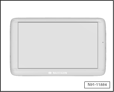
View of portable navigation and infotainment system -J982-
Features of portable navigation and infotainment system -J982-

Note
- When handling complaints, it is essential to know the function and operation of the portable navigation and infotainment system -J982-.
- Additional information → Owner's manual
- When carrying out repair work or fault finding, use the vehicle diagnostic tester in the "Guided fault finding" or "Guided functions" function.
- → Wiring diagrams, electrical fault finding and installation locations.
- When reconnecting the battery, remember to check the vehicle equipment (radio, clock, comfort electrics, etc.) in accordance with the repair manual and/or the owner's manual.
Features of portable navigation and infotainment system -J982-
The portable navigation and infotainment system -J982- offers a comprehensive range of functions and multimedia content.
The main features of the portable navigation and infotainment system -J982- are:
- General
- Navigation
- Hands-free system
- Radio functions
- Media functions
- Eco functions
- Trip computer
- Additional displays
General features:
- 5" TFT color display
- Resistive touch technology
- SD card/MP3
- Bluetooth
- Integrated microphone
- Integrated TMC tuner
Navigation functions:
- Multi-route guidance
- Destination entry on map
- TMC dynamic routing
- 2.5D bird's-eye view
- 2D detailed map
- 2D extended lane guidance
- Parking finder
- Filling station search when the fuel tank is empty
- Pedestrian mode
Hands-free system functions:
- SDS/TTS
- SMS
- Bluetooth (HFP, A2DP, AVRCP, PBAP)
- Phone mute
Radio functions
- CD player control
- Radio control
- Adjusting volume
- Adjusting sound settings
Media functions:
- Picture viewer
- Micro SD card
- Stereo audio (A2DP) transmission of audio signals via Bluetooth from a paired phone/MP3 player
- Media player control (AVRCP) transmission of video signals via Bluetooth from a paired phone/MP3 player
- SMS access (MAP) display and reading aloud of SMS messages. Replies are not possible
Eco functions:
- ECO monitor. Provides graphical feedback on ECO driving behavior
- ECO shift. Evaluation of gear-shifting behavior.
- ECO swim. Evaluation of anticipatory driving.
- ECO challenge/consumption. Evaluation of consumption against a specified ECO consumption target. Routes based on GPS are run against each other for consumption and time
Trip computer:
- Consumption
- Range
- Distance driven
- Average speed
Additional displays
- Tachometer
- Outside temperature
- Coolant temperature
- Upshift indicator
- Time
- PDC display
Fault finding
For fault finding, use the → Vehicle Diagnostic Tester in the "Guided Fault Finding" or "Guided Functions" function.
Installation locations overview - Radio / Radio navigation systems
Installation locations overview - "RCD 215" and portable navigation and infotainment system -J982-
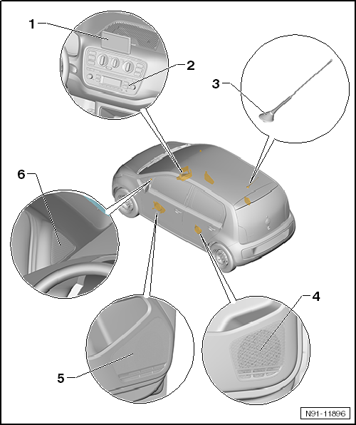
- portable navigation and infotainment system -J982-
- portable navigation and infotainment system -J982-
- Radio -R-
- RCD 215
- Remove and install
- Overview of connectors
- Anti-theft coding
- Antenna -R11-
- installed as a simple short rod antenna on the rear of the roof
- further information in the Antenna Systems section
- Woofer, rear right -R17- and woofer, rear left -R15-
- Installed in the side trim panels in the passenger compartment, left and right
- further information in the Sound System section
- Woofer, front right -R23- and woofer, front left -R21-
- installed in the doors, left and right
- Midrange tones are reproduced by the woofers and tweeters.
- further information in the Sound System section
- Tweeter, front right -R22- and tweeter, front left -R20-
- installed in the A-pillar trim, left and right
- further information in the Sound System section
Removing and installing radio / radio navigation systems
Removing and installing "RCD 215"
Required Special Tools, Test and Measuring Equipment and Auxiliary Items
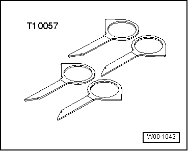
- Release tool for radio -T10057-
- Release Wedge -3409-
Removing:

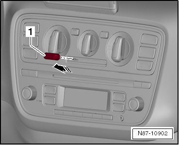
- Remove recirculation switch -1- in the direction of the arrow.
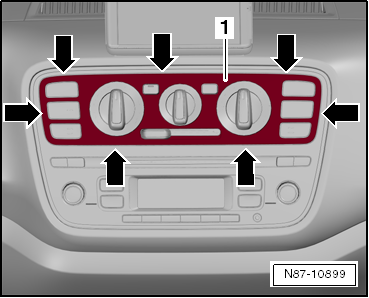
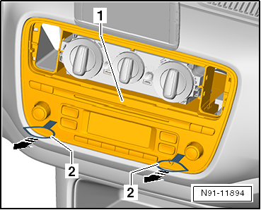
- Unclip trim panel -1- using trim removal wedge -3409- (arrows) and remove trim panel -1-.
- Unscrew bolts (1.5 N·m).
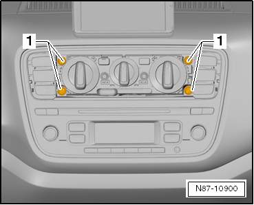
- Remove switch units (arrows) using trim removal wedge -3409- and disconnect the electrical connectors.

- Insert release tool for radio -T10057- into the openings provided (arrows) until it engages.
- Pull out radio together with trim panel and disconnect antenna connector.
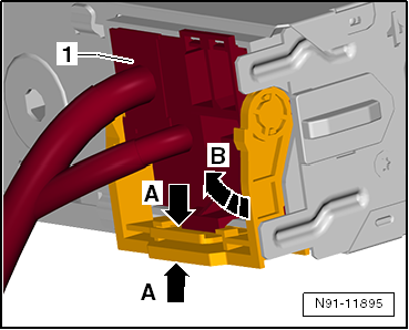
- Squeeze connector lock -A- and swing locking bracket in direction -B-.
Installing:
Installation is performed in the reverse order.
Removing and installing interface for portable navigation and infotainment system -J983-

Note
The interface for portable navigation and infotainment system -J983- must only be removed together with the wiring harness.

- Interface for portable navigation and infotainment system -J983-
- Junction point KSK roof antenna
- 12-pin connector integrated in the quad block connector on the radio
- Antenna connection on radio
- Antenna connector
- Antenna splitter
Removing:
- "Removing and installing radio / radio navigation systems"
- Remove operating and display unit for air conditioning → Air Conditioning.
or
- Remove operating and display unit for heater → Heater.
- Remove holder and, if fitted, portable navigation and infotainment system -J982-.
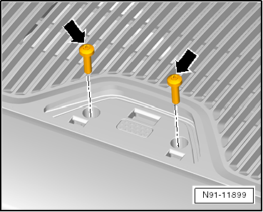
- Unscrew bolts -arrows-.
- Remove 12-pin connector from the quad block connector.
- Disconnect antenna cable from radio.
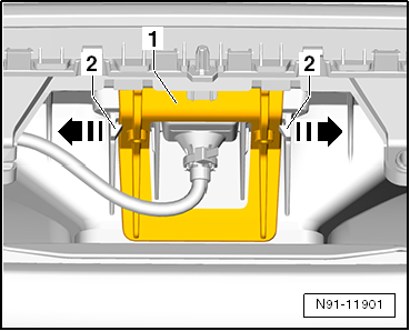
- Unclip retaining bracket -1- from holder -2-.
- Pull off wiring harness retaining clips.
- Remove interface for portable navigation and infotainment system -J983- together with the wiring harness, upwards.
Installing:
Installation is performed in the reverse order.

Note
When installing, make sure the cables are routed correctly to avoid damage.
Connector pin assignments
Pin assignment "RCD 215"
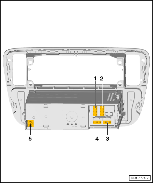
- Multiple connector 1, 8-pin, speaker outputs
- Contact assignment
- Multiple connector 2, 8-pin, power supply, CAN bus
- Contact assignment
- Multiple connector 3, 12-pin, telephone signal input, telephone mute
- Contact assignment
- Multiple connector 4, 12-pin, AUX input audio, CD changer control and CD audio input signals
- Contact assignment
- Connector 5, antenna connection
- Connector color beige
- Connection for antenna cable to antenna
Multiple connector 1, 8-pin, speaker outputs
- Speaker rear right, positive
- Speaker front right, positive
- Speaker front left, positive
- Speaker rear left, positive
- Speaker rear right, negative
- Speaker front right, negative
- Speaker front left, negative
- Speaker rear left, negative
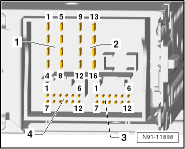
Multiple connector 2, 8-pin, power supply, CAN bus
- CAN bus High
- CAN bus Low
- not assigned
- Ground connection, terminal 31
- not assigned
- not assigned
- Positive connection, terminal 30
- Control signal for anti-theft coding, SAFE
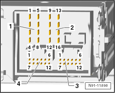
Multiple connector 3, 12-pin, telephone signal input, telephone mute
- 1-5 - not assigned
- 6 - Telephone AF signal input, negative
- 7-9 - not assigned
- 10 - Telephone Mute
- 11 - not assigned
- 12 - Telephone AF signal input, plus

Multi-pin connector 4, 12-pin, AUX audio input, CD changer control and CD audio input signal
- not assigned
- not assigned
- PID Audio, minus
- PID power supply, plus
- not assigned
- PID, Bus DATA OUT
- PID, minus
- PID Audio left
- PID Audio right
- PID control signal
- PID, Bus DATA IN
- not assigned
