Air Conditioner Diagnosis by Codes on the Display of Its Control Unit
GENERAL INFORMATION
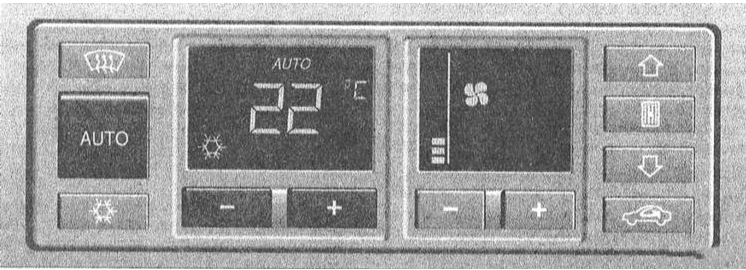
Automatic Climate Control Panel (control panel layout may vary)
· To change the channel number up or down, press the "+" or "–" button respectively. · To display information for the selected channel, press the recirculation button. · To exit the code reading mode, press the AUTO button or turn the ignition off. 6 A total of 61 channels is provided. While diagnostic information is displayed, the A/C continues to operate in the last selected mode.
(Air conditioner diagnostic codes read by a scan tool from the diagnostic connector are shown below)
DIAGNOSTIC PROCEDURE
PROCEDURE
1. Turn the ignition on or start the engine.
2. Press and hold the recirculation button.
3. Press and hold the upward airflow distribution button.
4. Release both buttons.
5. The channel number is shown on the display (01 for the first, 02 for the second, etc.).
Diagnostic channel number Display 1 System fault: fault code is displayed (code decoding is given below) 2 Under-headliner temperature sensor reading (G86) 3 Temperature sensor reading near instrument cluster (G56) 4 Air intake temperature sensor reading (G89) 5 Front outside air temperature sensor reading (G17) 6 Outside air temperature sensor reading 7 Temperature sensor reading for outside air supplied into cabin (G109) 8 Temperature value near the blend door actuator motor position sensor (G92) 9 Temperature value near the blend door 10 Fixed, unchanging blend door temperature value 11 Center blend door actuator motor position sensor reading (G112) 12 Required center blend door position value 13 Air distribution direction door actuator motor position sensor reading (windshield defrost/footwell airflow) (G114) 14 Required air distribution direction door position value 15 Air door actuator motor position sensor reading (G113) 16 Required air door position value 17 Vehicle speed (km/h) 18 Actual heater blower motor supply voltage (V) 19 Actual heater blower motor supply voltage (V) 20 A/C supply voltage (V) 21 Number of voltage drops (excluding short-term spikes) 22 Cyclically high reading of A/C refrigerant pressure sensor/switch (F118) 23 Cycles of high readings from A/C refrigerant pressure sensor/switch (F118) 24 Sensor/switch looping (without fluctuations) 25 Analog/digital form of kickdown mode activation switch reading 26 Analog/digital form of engine coolant temperature warning lamp reading 27 Coded value 28 Engine speed (rpm) 29 A/C compressor speed (rpm x 1.28) 30 Software version 31 Display test (all segments should light up) 32 Blend door position sensor fault counter 33 Center door position sensor fault counter 34 Air distribution direction door position sensor fault counter 35 Air door position sensor fault counter 36 Blend door position sensor cold stop value (G92) 37 Blend door position sensor hot stop value (G92) 38 Center door position sensor cold stop value (G112) 39 Center door position sensor hot stop value (G112) 40 Air distribution direction door position sensor cold stop value (G114) 41 Air distribution direction door position sensor hot stop value (G114) 42 Bypass door position sensor cold stop value (G113) 43 Bypass door position sensor hot stop value (G113) 44 Vehicle operating cycle counter 45 Calculated cabin temperature (numeric) 46 Calculated outside air temperature (filtered) 47 Outside air temperature (unfiltered, °C) 48 Outside air temperature (unfiltered, numeric) 49 Speedometer/VSS fault counter 50 Parking time (hours:minutes) 51 Engine coolant temperature, °C 52 Graphic channel 1 – refer to fault code decoding below
CAUTION
When channel 52 is selected, the display first shows the following pattern: "__ _". The electrical output signals of the A/C are identified by the illumination of specific signals on the display.53 Graphic channel 2 – refer to fault code decoding below
CAUTION
When channel 53 is selected, the display first shows the following pattern: "__ _". The electrical output signals of the A/C are identified by the illumination of specific signals on the display.54 Reference parameters 55 Outside air temperature in °C or °F depending on the A/C control knob selection 56 Under-headliner temperature sensor reading, °C (G86) 57 Under-dash temperature sensor reading, °C (G56) 58 Air intake temperature sensor reading, °C (G89) 59 Front outside air temperature sensor reading, °C (G17) 60 Blower temperature sensor reading, °C (G109) 61 Software version (latest)
Channel fault code decoding
Diagnostic channel 1
DTC Code Possible Cause of Failure
02.1 Open circuit in interior temperature sensor G86 (under headliner); default value on sensor failure: 128
02.2 Short circuit in interior temperature sensor G86 circuit; Sets DTC 02.1
02.3 Intermittent poor contact in interior temperature sensor G86 circuit
02.4 Intermittent short circuit in interior temperature sensor G86 circuit
03.1 Open circuit in instrument panel temperature sensor G56; Sets DTC 02.1
03.2 Short circuit in instrument panel temperature sensor G56 circuit; Sets DTC 02.1
03.3 Intermittent poor contact in instrument panel temperature sensor G56 circuit
03.4 Intermittent short circuit in instrument panel temperature sensor G56 circuit
04.1 Open circuit in intake air temperature sensor G89; if sensor fails, signal from sensor G17 is used; Sets DTC 04.1
04.2 Short circuit in intake air temperature sensor G89 circuit; Sets DTC 04.1
04.3 Intermittent poor contact in intake air temperature sensor G89 circuit
04.4 Intermittent short circuit in intake air temperature sensor G89 circuit
05.1 Open circuit in outside air temperature sensor G17; if sensor fails, signal from sensor G89 is used; Sets DTC 04.1
05.2 Short circuit in outside air temperature sensor G17 circuit; Sets DTC 05.1
05.3 Intermittent poor contact in outside air temperature sensor G17 circuit; default value on failure of both sensors (G89 and G17): 128
05.4 Intermittent short circuit in outside air temperature sensor G17 circuit
06.1 Open circuit in engine coolant temperature sensor (ECT) G110; if sensor is faulty or not installed, coolant temperature is calculated; diagnosis is possible only at temperatures above 0°C (32°F)
06.2 Short circuit in engine coolant temperature sensor (ECT) G110 circuit; Sets DTC 06.1
06.3 Intermittent poor contact in engine coolant temperature sensor (ECT) G110 circuit
06.4 Intermittent short circuit in engine coolant temperature sensor (ECT) G110 circuit
07.1 Open circuit in heater fan temperature sensor G109; programmed correct value = 0
07.2 Short circuit in heater fan temperature sensor G109 circuit; Sets DTC 07.1
07.3 Intermittent poor contact in heater fan temperature sensor G109 circuit
07.4 Intermittent short circuit in heater fan temperature sensor G109 circuit
08.1 Open circuit in air mix flap position sensor G92; automatic control of the drive electric motor is not possible, manual adjustment required
08.2 Short circuit in air mix flap position sensor G92 circuit; Sets DTC 08.1
08.3 Intermittent poor contact in air mix flap position sensor G92 circuit
08.4 Intermittent short circuit in air mix flap position sensor G92 circuit
08.5 Air mix flap position sensor G92 jammed; electric motor is looping, software attempts to clear the cause of the jam
08.6 Air mix flap position sensor G92 failure
08.7 Intermittent jam of air mix flap position sensor G92
11.1 Open circuit in center flap position sensor G112; automatic control of the drive electric motor is not possible, manual adjustment required
11.2 Short circuit in center flap position sensor G112 circuit; Sets DTC 11.1
11.3 Intermittent poor contact in center flap position sensor G112 circuit
11.4 Intermittent short circuit in center flap position sensor G112 circuit
11.5 Center flap position sensor G112 jammed; electric motor is looping, software attempts to clear the cause of the jam
11.6 Center flap position sensor G112 failure
11.7 Intermittent jam of center flap position sensor G112
13.1 Open circuit in airflow direction flap position sensor G114; automatic control of the drive electric motor is not possible, manual adjustment required
13.2 Short circuit in airflow direction flap position sensor G114 circuit; Sets DTC 13.1
13.3 Intermittent poor contact in airflow direction flap position sensor G114 circuit
13.4 Intermittent short circuit in airflow direction flap position sensor G114 circuit
13.5 Airflow direction flap position sensor G114 jammed; electric motor is looping, software attempts to clear the cause of the jam
13.6 Airflow direction flap position sensor G114 failure
13.7 Intermittent jam of airflow direction flap position sensor G114
15.1 Open circuit in bypass flap position sensor G113; on sensor failure, software sets an emergency value
15.2 Short circuit in bypass flap position sensor G113 circuit; Sets DTC 15.1
15.3 Intermittent poor contact in bypass flap position sensor G113 circuit
15.4 Intermittent short circuit in bypass flap position sensor G113 circuit
15.5 Bypass flap position sensor G113 jammed; electric motor is looping, software attempts to clear the cause of the jam
15.6 Bypass flap position sensor G113 failure
15.7 Intermittent jam of bypass flap position sensor G113
17.0 Vehicle speed sensor (VSS) failure
18.1 Constant incorrect supply voltage to fresh air blower
18.3 Intermittent incorrect supply voltage to fresh air blower
20.1 Constant incorrect supply voltage to A/C compressor; compressor switches on only if supply voltage is maintained at not less than 10.8 V for at least 25 seconds
20.3 Intermittent incorrect supply voltage to A/C compressor; compressor switches on only
22.1 Open circuit in A/C high-pressure refrigerant switch F118; compressor remains off as long as the switch is open
22.3 Intermittent poor contact in A/C high-pressure refrigerant switch F118 circuit
22.5 Open circuit 120X in A/C high-pressure refrigerant switch F118 circuit; compressor reactivation circuit, VAG 1551 scan tool function
29.1 Constant slight belt slip
29.2 Constant severe belt slip
29.3 Intermittent slight belt slip
29.4 Intermittent severe belt slip
Graphic Diagnostic Channel 52
CAUTION
The situation described below occurs when the A/C compressor is disconnected.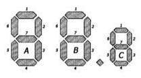
A/C Display Segments
Segment Group C. Illumination of a segment indicates:
1 Slipping or lock-up, cutout of 120x pressure switch for high refrigerant pressure 2 Engine speed dropped below 200 to 500 rpm 3 – 4 Engine speed exceeds 6000 rpm 5 – 6 – 7 System is functioning normally1)
Segment Group B. Illumination of a segment indicates:
1 A/C switched off manually (stand-by function disabled) 2 Voltage too low 3 Kickdown mode activation switch (via TCM, compressor switched off for max. 12 seconds) 4 Engine coolant temperature warning lamp switch 5 Low refrigerant pressure switch, A/C F73 6 High refrigerant pressure switch, A/C F118 7 System is functioning normally1)
1) When the system is functioning properly, segments C7, B7 and A7 must illuminate simultaneously.
Segment Group A. Illumination of a segment indicates:
1 Economy mode (ECON) detected 2 Shutdown detected 3 Outside air temperature too low 4 Engine control system (compressor remains off for 3 to 12 seconds) 5 Pressure remains elevated for more than 30 seconds 6 Blower air temperature sensor reads less than –3°C (27°F) 7 System is functioning normally1) Divider point visible: compressor is on. Divider point not visible: compressor is off.
1) When the system is functioning properly, segments C7, B7 and A7 must illuminate simultaneously.
Graphic Diagnostic Channel 53
CAUTION
The situation described below occurs when the A/C compressor is disconnected.Segment Group C. Illumination of a segment indicates:
1 Fan for cabin temperature sensor 2 Recirculation air flap closed (recirculation mode) 3 Heat exchanger valve closed 4 Bidirectional wiring harness 5 A/C compressor switched on 6 Heater blower first speed switched on 7 System is functioning normally1)
Segment Group B. Illumination of a segment indicates:
1 – 2 Air flap open 3 Air flap closed d2 4 – 5 Air distribution flap is in the footwell airflow position 6 Air distribution flap is in the windshield defrost position 7 System is functioning normally1)
Segment Group A. Illumination of a segment indicates:
1 – 2 Center air flap is in the airflow position to the dashboard vents 3 Center air flap is in the airflow position to the windshield defrost and footwells 4 – 5 Mix air flap is in the cold air position 6 Mix air flap is in the warm air position 7 System is functioning normally1)
1) When the system is functioning properly, segments C7, B7 and A7 must illuminate simultaneously.
Test yourself
A quick Audi A3 quiz: every answer comes with an explanation and a link to the manual page.