Safety Precautions to Prevent Damage to the Catalytic Converter
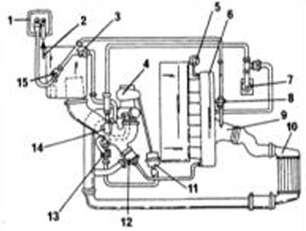 Turbocharger system diagram 1 - activated charcoal canister 2 - vent line from fuel tank 3 - check valve for activated charcoal canister 4 - exhaust-driven turbocharger 5 - fuel pressure regulator 6 - intake line (fuel line) 7 - crankcase ventilation 8 - check valve for activated charcoal canister 9 - connection on throttle body 10 - intercooler (charge air cooler) 11 - intercooler receiver 12 - overrun cut-off valve 13 - solenoid valve for boost pressure limitation 14 - crankcase ventilation pressure limiting valve 15 - electrically controlled activated charcoal canister valve
To prevent damage to the oxygen sensor and catalytic converter, observe the following requirements:
Petrol engines
– Always use only unleaded gasoline. – Starting a warm gasoline engine by pushing or towing is permitted only in one attempt and over a distance of no more than 50 m. It is preferable to use a jumper cable for this purpose. Unburned fuel may ignite and cause the catalytic converter to overheat and be destroyed.
CAUTION
For technical reasons, starting vehicles with AT is not possible.- If the engine is difficult to start, do not crank the starter motor for an extended period. Fuel is injected continuously during cranking. Identify and correct the cause of the malfunction. - When diagnosing ignition system malfunctions, eliminate fuel injection during cranking. To do this, disconnect the fuel pump relay. - Never run the fuel tank completely dry. - If ignition misfires occur, do not increase engine speed; correct the malfunction immediately. - Use only recommended spark plugs. - Do not check for spark with the spark plug connector disconnected. - Do not perform a cylinder power balance test by disconnecting the spark plug lead from its spark plug. Unburned fuel will enter the catalytic converter. - Do not park the vehicle over dry leaves or grass. The exhaust system in the area of the catalytic converter is very hot and radiates heat even after the engine has been switched off. - Do not apply underbody protection coatings to exhaust system components. - Do not modify the design of the heat shields. - When filling the engine with oil, pay particular attention
CAUTION
Make sure that the level does not exceed the mark indicated on the dipstick as Max. Excess oil enters the catalytic converter as a result of incomplete combustion and may damage its precious metal coating or completely destroy the catalytic converter.Turbocharger
Gasoline engines 1.8 L 150 L hp are equipped with a turbocharger.
The turbocharger has two turbines mounted on a common shaft and located in two separate housings: the drive turbine, driven by the exhaust gases, and the compressor turbine, which compresses the air supplied to the engine. The angular speed of the turbine shaft reaches 120,000 rpm. The turbocharger is lubricated by the engine lubrication system. The turbocharger is additionally cooled by the engine coolant.
Turbocharging can increase engine output by up to 100 %. The power increase depends, among other things, on the boost pressure, which for passenger car engines is 0.4 – 0.8 bar (tire pressure is 1.8 bar). Boost pressure is monitored by a sensor. If the boost pressure exceeds the specified value, the pressure control valve opens to reduce it.
Along with the increase in output, the use of a turbocharger also increases torque, which primarily improves engine flexibility. A prerequisite for reliable boost is that the turbocharger rotates at the required speed. For this reason, the engine is fitted with a relatively small turbocharger that begins to operate at low engine speeds and increases its torque.
An intercooler (charge air cooler) is located between the turbocharger and the engine intake tract. Cooling the air increases engine output, since cold air has a higher density and therefore contains more oxygen.
In the diesel engine, the variable geometry turbocharger (VGT) increases engine output. The vanes are smoothly adjusted by the engine control system through a solenoid valve and a vacuum actuator. As a result, optimum boost pressure is achieved at any engine speed, thereby increasing engine output, particularly at low engine speeds.
The turbocharger is a precision component. Therefore, if a malfunction occurs, the turbocharger must generally be replaced.
Turbocharger Malfunctions
If the turbocharger is not operating correctly, this may be indicated by reduced engine output or the inability to reach maximum speed, assuming the fuel injection system is operating normally. This may be caused by a leak in the system or a turbocharger malfunction. The following checks are recommended:
System Leaks
Inspect the air hose between the turbocharger and the intake manifold via the intercooler for kinks, cracks, loose connections, etc. If any are found, correct them. Check for leaks between the cylinder head and the intake manifold. These may be caused by defective gaskets or, in some cases, by a displaced manifold. Leaks may also occur at the connecting flanges between the exhaust manifold and the cylinder head, or between the exhaust manifold and the turbocharger.
Faulty Turbocharger
Check the boost pressure at the workshop. It may be either too high or too low. If the pressure is too high, the cause may be a faulty boost pressure limiting solenoid valve or a faulty wastegate actuator. Reading the stored fault codes with the diagnostic tester will help determine where the malfunction is.
If the pressure is too low, suspect the wastegate actuator. Otherwise, the turbocharger itself must be faulty.
TURBOCHARGER REMOVAL AND INSTALLATION
As is known, after a long drive at high speed the engine must not be switched off immediately; it should be allowed to run at idle for a short time. The reason is as follows: if an "overheated" engine is switched off immediately, the turbocharger shaft bearing becomes so hot that the lubricating oil in the bearing may burn. With such treatment and subsequent restarting, the turbocharger will soon fail.
The turbocharger is quite sensitive to dirt and foreign objects, so cleanliness must be maintained during removal and installation.
PROCEDURE
1. Disconnect the negative battery cable (do not forget the radio anti-theft code).
2. Remove the air hose from the turbocharger.
3. Pinch off the coolant hose leading to the turbocharger using a hose clamp, or drain the coolant.
4. Raise the front of the vehicle and support it on stands.
5. Disconnect the exhaust system bracket from the transmission. Disconnect the catalytic converter from the turbocharger (4 nuts). Disconnect the oil supply and oil return lines from the turbocharger. Take care to minimize oil leakage. From the underside, unscrew the turbocharger mounting bolts from the exhaust manifold. These bolts are difficult to reach, so use a suitable wrench (12 mm box-end wrench). Hold the turbocharger while removing the bolts, and once all bolts are removed, pull the turbocharger upward. Installation is performed in the reverse order of removal. Always use new nuts and bolts. Before connecting the oil supply line, pour some oil into the turbocharger (pre-lubrication). Initially, do not allow the engine to run at high speed.
Test yourself
A quick Audi A3 quiz: every answer comes with an explanation and a link to the manual page.