General: hydraulic suspension
PREAMBLE
Depending on the trim level, the vehicle is fitted with one of two types of self-leveling suspension.
Hydractive 3 hydraulic suspension
Hydractive 3 suspension is fitted with 2 spheres per axle.
Hydractive 3 suspension is controlled according to vehicle speed and road condition.
Hydractive 3+ hydraulic suspension
Hydractive 3+ suspension is fitted with 3 spheres per axle.
Hydractive 3+ suspension is controlled according to vehicle speed, road condition and the driver's driving style.
Vehicles fitted with xenon headlamps must be fitted with Hydractive 3+ suspension and a dynamic headlamp levelling corrector, managed by the suspension ECU.
HYDRAULIC COMPONENTS
The hydraulic components are as follows:
- hydraulic fluid,
- hydraulic reservoir,
- integrated hydro-electronic unit,
- hydraulic unions,
- spheres and dished plates,
- height sensors,
- Pulsed height control,
- Steering wheel angle sensor (Hydractive 3+),
- Stiffness regulators (Hydractive 3+).
Hydraulic fluid
The suspension fluid, LDS (Steering and Suspension Fluid), is orange in colour and 100% synthetic.
The LDS hydraulic fluid is not miscible with LHM hydraulic fluid.
The LDS suspension fluid is supplied in 1 litre containers.
Integrated hydro-electronic unit
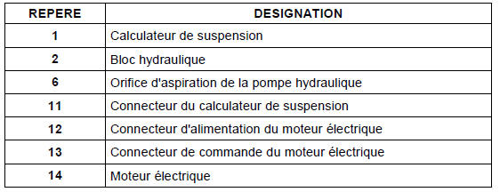
The integrated hydro-electronic unit is a one-piece, non-dismountable assembly made up of the following components:
- an electric motor to drive the hydraulic pump,
- a 5-piston axial hydraulic pump,
- an anti-pulsation accumulator and flow regulator,
- 4 solenoid valves: 2 per axle, 1 for intake (vehicle raising), 1 for exhaust (vehicle lowering),
- an electronic suspension control unit,
- 2 anti-sag check valves,
- 6 hydraulic fluid filters: upstream and downstream of the solenoid valves,
- One pressure relief valve.
Location of the integrated hydro-electronic unit
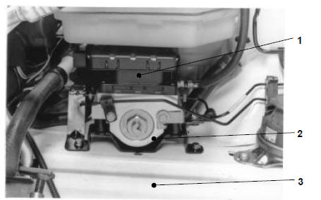
Installation of the integrated hydraulic electronic unit

Internal diagram of the integrated hydraulic electronic unit
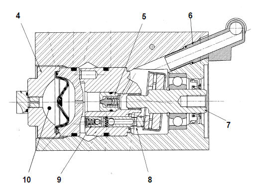
Internal diagram of the integrated hydraulic electronic unit
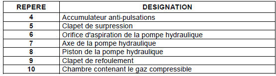
Overview of the integrated hydraulic electronic unit
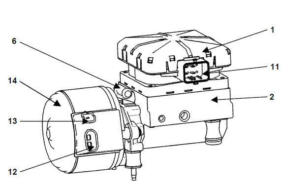
Overview of the integrated hydraulic electronic unit
Hydraulic fluid reservoir
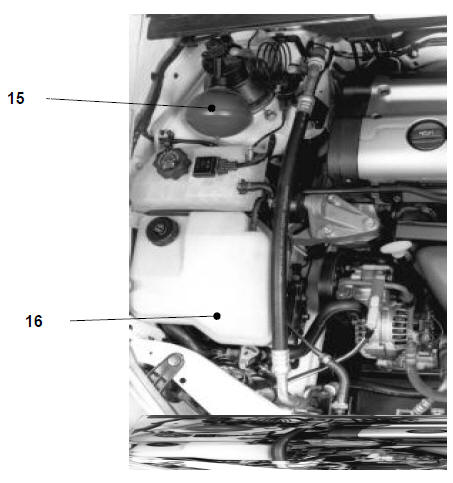
Hydraulic fluid reservoir

The plastic hydraulic fluid reservoir is fitted with a 50 μm filter.
The capacity of the hydraulic circuit is approximately 4.8 litres.
The hydraulic fluid level can be read through a window on the hydraulic fluid reservoir.
Suspension sphere (saucer type)
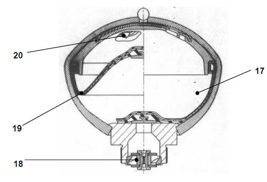
Suspension sphere (saucer type)
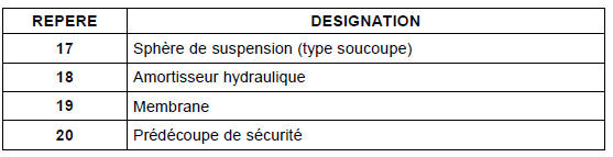
The suspension spheres are of the "saucer" type.
The suspension spheres use a multi-layer diaphragm, giving them an unlimited service life.
A safety pre-cut is made in the upper part of the sphere.
In the event of bursting from overpressure, the pre-cut prevents metal fragments from being ejected.
Stiffness regulator
Stiffness regulator
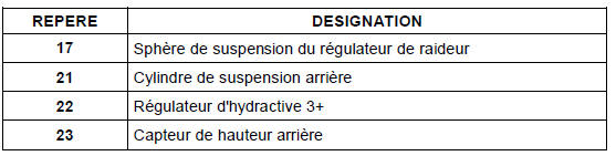
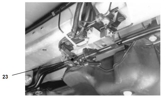
Height sensor

Ride height push button (momentary)
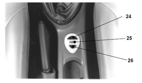
Ride height push button (momentary)
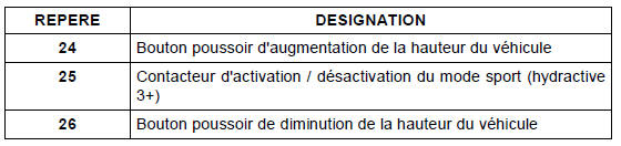
The vehicle ride height button is an electric momentary-type push button.
The sport mode activation / deactivation switch is of the momentary type.
Steering wheel angle sensor
A steering wheel angle sensor is integrated in the steering column switch module.
The steering wheel angle sensor is not multiplexed in the version without dynamic stability control.
The steering wheel angle sensor is multiplexed in the version with dynamic stability control.
DIAGRAM
Hydractive 3
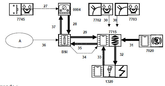
Hydractive 3
Key:
- Single arrow: wired link
- Triple arrow: multiplexed link
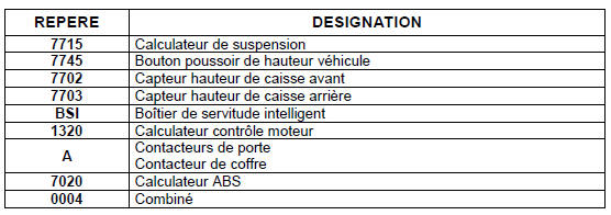
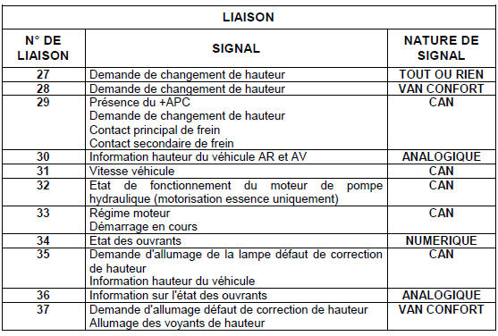
Hydractive 3 +
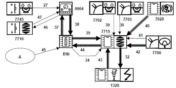
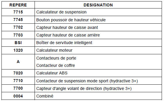
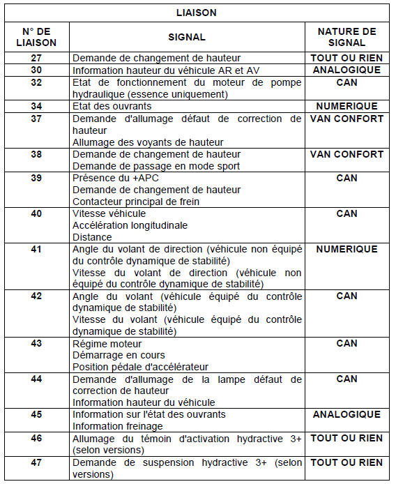
Hydractive 3 +
Key:
- Single arrow: wired link
- Triple arrow: multiplexed link
Test yourself
A quick Citroen C5 Aircross quiz: every answer comes with an explanation and a link to the manual page.