Electronic Control Unit
GENERAL INFORMATION
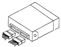
Electronic Control Unit (ECU)
The Electronic Control Unit (ECU) is located behind the trim panel on the right-hand side
of the passenger compartment. The ECU is the main component of the fuel injection system..
The ECU constantly receives signals from various sensors and controls the most important engine systems and components. In addition, the ECU performs the function of
diagnosing faults in engine systems and components. If a fault is detected, the ECU turns on the "Service Engine Soon" indicator and stores the corresponding fault code(s) in memory. This
facilitates subsequent fault diagnosis. The vehicle is equipped with an IEFI-
6. If the ECU fails, it is replaced as an assembly, since it contains no
serviceable components. Control parameters and algorithms are stored in the
erasable programmable read-only memory (EPROM). The program version stored in the ROM is designated by the ECU number, which corresponds to the
vehicle identification number..
The ECU supplies power to various sensors and switches with a constant
voltage of 5 and 12 V. The ECU electrical circuits have high resistance, so when the power terminals are connected to a test lamp, the lamp will not light.
For accurate measurement of supply voltage, use a digital voltmeter with high input impedance (10 MOhm). The ECU controls the operation of fuel
injectors, idle air control valve, compressor clutch, etc. by means of
special electronic devices (4-channel drivers) designed to process the ECU output control signals..
The ECU is maintenance-free. Therefore, if the ECU fails, it must be replaced as an assembly. Warning.
When replacing a factory-installed ECU, transfer the
code and serial number of the old ECU to the plate of the new ECU. Do not make any marks on the housing.
ECU. This information may be required for future vehicle operation. To prevent ECU damage, any operations involving switching
ECU power wires, for example connecting or disconnecting ECU connectors,
fuse, battery cables, extension wires, etc.),
must only be performed with the ignition switched OFF..
Remove or disconnect:
PROCEDURE.
1. Disconnect the negative battery cable.
2. Remove the cover panel of the ECU..
3. Remove the ECU from its mounting and disconnect the connectors..
Warning.
To prevent ECU damage from static electricity discharge,
do not touch the connector pins or soldered components..
Installation
PROCEDURE.
1. Insert the ECU into its mounting and connect the connectors..
2. Install the cover panel in place..
3. Connect the negative battery cable..
Checking operation.
PROCEDURE.
1. Turn the ignition ON..
2. Enter diagnostic mode..
2a. Output code 12 four times in succession to confirm there are no other fault codes in ECU memory. Code 12 confirms normal operation.
ECU..
2b. If fault code 51 is output or the Service Engine Soon indicator stays on with no codes present, the ECU is faulty..
Warning.
When replacing the ECU, perform all removal and installation operations in
accordance with the instructions given above.
Test yourself
A quick Daewoo Nexia quiz: every answer comes with an explanation and a link to the manual page.