Brake System
Front Disc Brake Repair Procedures
In this manual: Brake System
29steps
~179min
5/5difficulty
1special tools
Done 0 of 29
Removal
- Loosen the wheel nuts slightly. Raise the vehicle and make sure it is securely supported.
- Remove the front wheel and tire (A) from the front hub.
Tightening torque: 107.9 - 128 N·m


- Be careful not to damage the hub bolts when removing the front wheel and tire (A).
- Loosen the brake hose mounting bolt and remove the brake hose bracket.
Tightening torque: 8.8 - 13.7 N·m

- Lower the caliper body by loosening the guide rod bolt.
Tightening torque: 2.2 - 3.2 kgf·m
- Remove the pad return spring (A).

- Pad return springs must be replaced with new ones every time the pads are replaced.
- Technicians must be careful not to deform the pad return springs.
- Deformed pad return springs may cause improper braking and increased fuel consumption.
- Remove the brake pad.

- Separate the pad retainer. Then remove the caliper support by loosening the caliper support bolts.
Tightening torque: 78.5 - 98 N·m

- Remove the front brake disc by loosening the screws (A).
Tightening torque: 4.9 - 5.9 N·m

Replacement
- Loosen the brake hose mounting bolt and remove the brake hose bracket.
Tightening torque: 8.8 - 13.7 N·m
- Lower the caliper body by loosening the guide rod bolt.
Tightening torque: 2.2 - 3.2 kgf·m
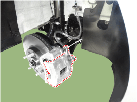
- Remove the pad return spring (A).
- Pad return springs must be replaced with new ones every time the pads are replaced.
- Technicians must be careful not to deform the pad return springs.
- Deformed pad return springs may cause improper braking and increased fuel consumption.
- Replace the brake pad with a new one.
- Install the pad return spring (A).
- Pad return springs must be replaced with new ones every time the pads are replaced.
- Technicians must be careful not to deform the pad return springs.
- Deformed pad return springs may cause improper braking and increased fuel consumption.
- Use SST (09581-2T100) when installing the brake caliper assembly.

- Connect the air hose (B) to the SST after making sure the SST valve is securely closed.
- Connect the SST to the caliper and press the piston of the caliper while slowly opening the SST valve counterclockwise.
- Close the SST valve (A) and disconnect the air hose (B). Then reopen the valve to release the remaining air and remove the SST from the caliper.
- Install the caliper body (A), then tighten the guide rod bolt (B).
Tightening torque: 21.6 ~ 31 N·m

- Install the brake hose mounting bolt with the brake hose bracket to the shock absorber.
Tightening torque: 8.8 - 13.7 N·m
Inspection
Front Brake Disc Thickness Inspection- Inspect the brake pads for wear and discoloration.
- Inspect the brake disc for damage and cracks.
- Remove all rust and contamination from the surface and measure the disc thickness at at least 8 points spaced equally (5 mm) from the outer edge of the brake disc. Front brake disc thickness - Standard: 23 mm (0.91 in.) - Service limit: 21.4 mm (0.84 in.) Runout: less than 0.005 mm (0.0002 in.)

- If wear exceeds the limit, replace the discs and pads as a set on both the left and right sides of the vehicle.
- Inspect the pad wear. Measure the pad thickness and replace the pad if it is less than the specified value. Pad thickness Standard: 11 mm (0.43 in.) Maximum operating limit: 2.0 mm (0.0787 in.)
- Make sure grease is applied to the sliding contact points, as well as to the abutment and metal backing, and check for damage.

- Position a dial indicator approximately 5 mm (0.2 in.) from the outer edge of the brake disc and measure the disc runout.
Brake disc runout Limit: 0.04 mm (0.0016 in.) or less (new)
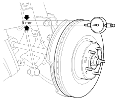
- If brake disc runout exceeds the limit, replace the disc, then measure the runout again.
- If runout does not exceed the limit, install the brake disc rotated 180°, then inspect the brake disc runout again.
- If runout cannot be corrected by changing the brake disc position, replace the brake disc.
Installation
- To install, reverse the removal procedure.
- Use SST 09581-2T100 when installing the brake caliper assembly.
- Connect the air hose (B) to the SST after making sure the SST valve is securely closed.
- Connect the SST to the caliper and press the piston of the caliper while slowly opening the SST valve counterclockwise.
- Close the SST valve (A) and disconnect the air hose (B). Then reopen the valve to release the remaining air and remove the SST from the caliper.
- After installation, bleed the brake system. (Refer to Brake System - "Brake Bleeding") (Refer to Brake System - "ABS Bleeding") (Refer to Brake System - "ESP Bleeding")
Test yourself
A quick Hyundai Elantra AD quiz: every answer comes with an explanation and a link to the manual page.
Was this page helpful?