Use fender covers to avoid damaging painted surfaces.
To avoid damage, carefully disconnect the wiring connectors by holding the connector body.
Label all wires and hoses to avoid incorrect connection.
Inspect the timing chain before removing the cylinder head.
Turn the crankshaft pulley so that the No. 1 piston is at top dead center.
Remove the engine assembly from the vehicle. (Refer to Engine and Transaxle Assembly - "Engine and Transaxle Assembly")
Remove the drive plate and adapter plate. (Refer to Cylinder Block - "Drive Plate")
Mount the engine on an engine stand for disassembly.
Remove the exhaust manifold. (Refer to Intake and Exhaust System - "Exhaust Manifold")
Remove the intake manifold. (Refer to Intake and Exhaust Systems — Intake Manifold)
Remove the timing chain. (Refer to Valve Timing System - Timing Chain)
Remove the water temperature control unit. (Refer to Cooling System - "Water Temperature Control Assembly")
Remove the cylinder head. (Refer to Cylinder Head Assembly - "Cylinder Head")
Remove the oil pump. (Refer to Lubrication System - "Oil Pump")
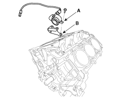
Remove the oil cap (A) and gasket (B).
Remove the water jacket spacer. (Refer to Cylinder Block - "Water Jacket Spacer")
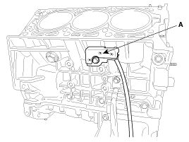
Remove the knock sensor.
Remove the upper oil pan. (Refer to Lubrication System - "Oil Pan")
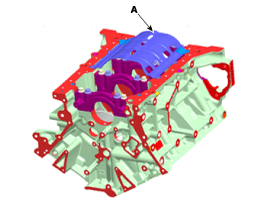
Remove the baffle (A).
Remove the rear oil seal retainer (A).
Remove the plug bolt (A) and washer gasket (B).
Check the oil clearance of the connecting rod cap.
Remove the piston and connecting rod assembly.
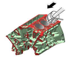
Using a ridge reamer, remove all carbon from the upper part of the cylinder.
Push the piston, connecting rod assembly, and upper bearing out through the top of the cylinder block.
Keep the bearings, connecting rod, and cap together.
Arrange the piston and connecting rod assemblies in the correct order.
Remove the main bearing cap and check the oil clearance.
Check the crankshaft end play.
Remove the crankshaft (A).
Arrange the main bearings and thrust bearings in the correct order.
Remove the oil jets (A).
Disassemble the piston rings.
Using a piston ring expander, remove the 2 compression rings (A).
Remove the oil control ring and expander spring (B) by hand.
Keep the piston rings only in the correct order.
Remove the snap rings from both ends of the piston pin, then push out the piston pin to separate the connecting rod.
Inspection
Connecting Rod
Check the connecting rod side clearance. Using a feeler gauge, measure the axial play while moving the connecting rod back and forth.
Standard clearance: 0.1 ~ 0.25 mm (0.004 ~ 0.010 in.)
A.
If the connecting rod side clearance is out of specification, replace the connecting rod.
B.
If the crankshaft is still out of specification after replacing the connecting rod, replace the crankshaft.
Check the connecting rod bearing oil clearance.
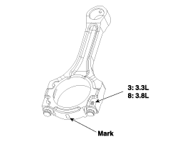
Make sure the alignment marks on the connecting rod and cap are aligned for correct reassembly.
Remove the 2 connecting rod cap bolts.
Remove the connecting rod cap and bearing half.
Clean the crankshaft journal and bearing.
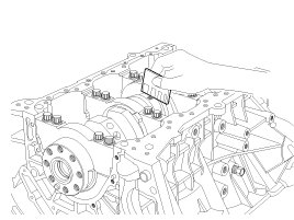
Place a piece of Plastigage across the connecting rod journal.
Install the bearing half and cap, then tighten the bolts to the specified torque. Tightening torque: [27.5 ~ 31 N·m] + [68 ~ 72°]
Do not rotate the crankshaft.
Remove the connecting rod cap again.
Measure the Plastigage at its widest point.
Standard oil clearance: 0.028 ~ 0.046 mm (0.0011 ~ 0.0018 in.)
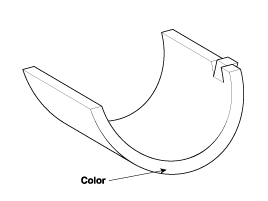
If the Plastigage width is too wide or too narrow, remove the upper bearing half, install a new bearing assembly with the same color code (select the color as shown in the following column), and recheck the clearance.
Do not grind, shim or scrape the bearings or caps to adjust the clearance.
If the Plastigage indicates that the clearance is still incorrect, try the next larger or smaller bearing (the color one step above or below the one indicated) and recheck the clearance.
If the proper clearance cannot be obtained using the correct larger or smaller size bearings, replace the crankshaft and start over.
If the marks are illegible due to accumulated dirt and dust, do not clean them with a wire brush or scraper. Clean them only with solvent or detergent.
Location of connecting rod mark Connecting Rod Identification
Grade
Mark
Inner Diameter
0
a
58.000 ~ 58.006 mm (2.2834 ~ 2.2837 in.)
1
D
58.006 ~ 58.012 mm (2.2837 ~ 2.2839 in.)
2
c
58.012 ~ 58.018 mm (2.2839 ~ 2.2842 in.)
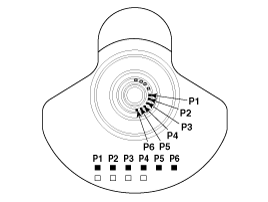
Location of crankshaft pin mark Crankshaft Identification Crankshaft Identification
Grade
Mark
Pin Outside Diameter
I
1 or A
54.966 ~ 54.972 mm (2.1640 ~ 2.1642 in.)
II
2 or B
54.960 ~ 54.966 mm (2.1638 ~ 2.1640 in.)
III
3 or C
54.954 ~ 54.960 mm (2.1635 ~ 2.1638 in.)
Location of identification mark (connecting rod bearing) Connecting Rod Bearing Identification
Grade
Mark
Bearing Thickness
E
BLUE
1.509 ~ 1.512 (0.05941 ~ 0.05953 in.)
D
BLACK
1.506 ~ 1.509 (0.05929 ~ 0.05941 in.)
C
RED
1.503 ~ 1.506 (0.05917 ~ 0.05929 in.)
B
GREEN
1.500 ~ 1.503 (0.05906 ~ 0.05917 in.)
A
YELLOW
1.497 ~ 1.500 (0.05894 ~ 0.05906 in.)
Selection
?
Connecting Rod Marking
0 (a)
1 (b)
2 (c)
Crankshaft Marking
1 or A
A (YELLOW)
B (GREEN)
C (RED)
2 or B
B (GREEN)
C (RED)
D (BLACK)
3 or C
C (RED)
D (BLACK)
E (BLUE)
Inspect the connecting rod.
When reinstalling, check the cylinder numbers on the connecting rods and caps. When installing a new connecting rod, the bearing locking grooves on the connecting rods and caps must face the same direction.
If one or both edges of the connecting rod thrust surface are damaged, replace the connecting rod. If the inner surface of the connecting rod is damaged or rough, also replace it.
Using a connecting rod alignment fixture, measure the bend or twist of the connecting rod. If the measured value is not within specification, correct the connecting rod using a press. If the connecting rod is severely bent or twisted, replace it. Maximum connecting rod bend: 0.05 mm/100 mm (0.0020 in./3.9370 in.) Maximum connecting rod twist: 0.1 mm/100 mm (0.0039 in./3.9370 in.)
When assembling the connecting rod without a bearing, there should be no difference.
Clean the piston
Using a gasket scraper, remove carbon deposits from the top of the piston.
Using a ring groove cleaning tool, clean the piston ring grooves.
Using solvent and a brush, thoroughly clean the piston.
Do not use a wire brush.
Check the piston-to-cylinder clearance by calculating the difference between the cylinder bore inside diameter and the piston outside diameter.
Piston-to-cylinder clearance: 0.03 ~ 0.05 mm (0.0012 ~ 0.0020 in.)
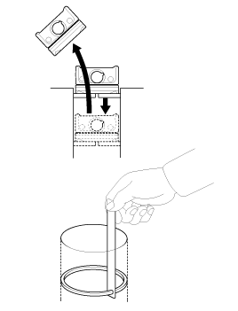
Inspect the cylinder bore diameter. Using a cylinder gauge, measure the cylinder bore diameter at the positions in the axial and thrust directions.
Standard diameter: 96.00 ~ 96.03 mm (3.7795 ~ 3.7807 in.)
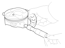
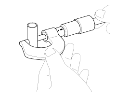
Measure the piston outer diameter at 3.8 L: 16 mm (0.6299 in.) from the bottom of the piston.
Standard diameter: 95.96 ~ 95.99 mm (3.7779 ~ 3.7791 in.)
Select a piston that matches the cylinder bore size class.
Piston-to-cylinder clearance: 0.03 ~ 0.05 mm (0.0012 ~ 0.0020 in.)
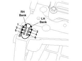
Check the cylinder bore size code stamped on the side of the cylinder block. Cylinder Bore Size Identification
Grade
Size code
Cylinder Inner Diameter
A
A
96.00 ~ 96.01 mm (3.7795 ~ 3.7799 in.)
B
B
96.01 ~ 96.02 mm (3.7799 ~ 3.7803 in.)
C
C
96.02 ~ 96.03 mm (3.7803 ~ 3.7807 in.)
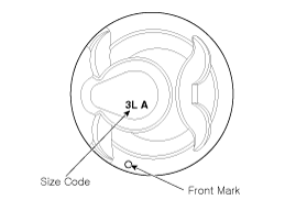
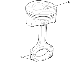
Check the piston size code (A) and front mark (B) on the top surface of the piston. Piston Outer Diameter Identification
Grade
Mark
3.8 L
A
A
95.96 ~ 95.97 mm (3.7779 ~ 3.7783 in.)
B
B
95.97 ~ 95.98 mm (3.7783 ~ 3.7787 in.)
C
C
95.98 ~ 95.99 mm (3.7787 ~ 3.7791 in.)
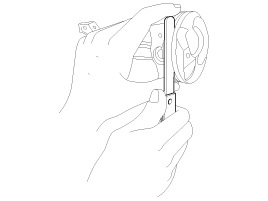
Check the piston ring side clearance. Using a feeler gauge, measure the clearance between a new piston ring and the ring groove wall. Piston ring side clearance Standard No. 1: 0.06 ~ 0.09 mm (0.0024 ~ 0.0035 in.) No. 2: 0.04 ~ 0.08 mm (0.0016 ~ 0.0031 in.) Oil ring: 0.02 ~ 0.065 mm (0.0008 ~ 0.0026 in.) Limit No. 1: 0.1 mm (0.0039 in.) No. 2: 0.1 mm (0.0039 in.) Oil ring: 0.2 mm (0.0079 in.)If the clearance exceeds the maximum limit, replace the piston.
Inspect the piston ring end gap. To measure the piston ring end gap, insert the piston ring into the cylinder bore. Position the ring at a right angle to the cylinder wall by carefully pushing it in with the piston. Measure the gap using a feeler gauge. If the gap exceeds the limit, replace the piston ring. If the gap is too large, recheck the cylinder bore diameter against the wear limit. If the bore diameter exceeds the service limit, replace the cylinder block. Piston ring end gap Standard No. 1: 0.17 ~ 0.32 mm (0.0067 ~ 0.0126 in.) No. 2: 0.32 ~ 0.47 mm (0.0126 ~ 0.0185 in.) Oil ring: 0.2 ~ 0.5 mm (0.0079 ~ 0.0197 in.) Limit No. 1: 0.6 mm (0.0236 in.) No. 2: 0.7 mm (0.0275 in.) Oil ring: 0.8 mm (0.0315 in.)
Measure the clearance between the piston pin and piston. Piston pin-to-piston clearance: 0.004 ~ 0.013 mm (0.0002 ~ 0.0005 in.)
Check the difference between the piston pin diameter and the connecting rod small end bore. Piston pin-to-connecting rod interference: 0.005 ~ 0.019 mm (0.0002 ~ -0.0007 in.)
Piston Piston Rings Piston Pins
Installation
Thoroughly clean all parts to be assembled.
Before installing parts, apply new engine oil to all sliding and rotating surfaces.
Replace all gaskets, O-rings, and oil seals with new parts.
Assemble the piston and connecting rod.
Install the piston pin with the 2EA snap ring and carefully check the snap ring assembly.
The front mark on the piston (A) and the front mark on the connecting rod (B) must face the engine toward the timing belt side.
Install the piston rings.
Install the cylindrical spring and oil control ring by hand.
Using a piston ring expander, install the 2 compression rings with the code mark facing up.
Install the piston rings so that the ring ends are positioned as shown below.
Install the connecting rod bearings.
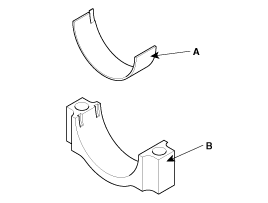
Align the bearing tang with the groove in the connecting rod or connecting rod cap.
Install the bearings (A) into the connecting rod and the connecting rod cap (B).
When assembling the connecting rods and caps, make sure that each connecting rod and connecting rod cap are in their original positions.
Install the piston and connecting rod assembly.
Before installing the pistons, apply a coat of engine oil to the ring grooves and cylinder bores.
Install the ring compressor, make sure the bearing is securely in place, then place the piston into the cylinder and tap it in using the wooden handle of a hammer.
Stop after the ring compressor is released, and check the connecting rod and journal alignment before inserting the piston into position.
Apply engine oil to the bolt threads. Install the connecting rod caps with bearings and tighten the bolts. Tightening torque: [27.5 ~ 31 N·m] + [68 ~ 72°]
Always use new connecting rod cap bolts. Connecting rod cap bolts are torque-to-yield bolts designed to stretch permanently beyond the elastic range when tightened. Therefore, if the bolts are removed and reused, they may break or fail to maintain clamping force.
Maintain downward pressure on the ring compressor to prevent the rings from expanding before they enter the cylinder bore.
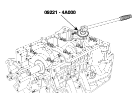
Using SST (09221-4A000), install the connecting rod bearing cap bolts.
Install the connecting rod caps and check the oil clearance.
Check the connecting rod side clearance.
Install the rear oil seal. (Refer to Cylinder Block - Rear Oil Seal)
Install the baffle plate. When installing the baffle plate bolts, tighten the bolts in two or three steps in the sequence shown below.
Tightening torque: 9.8 ~ 11.8 N·m
Assemble the remaining components in the reverse order of removal.
?
Test yourself
A quick Hyundai Genesis DH quiz: every answer comes with an explanation and a link to the manual page.