Brake System
Stop Lamp Switch Repair Procedures
In this manual: Brake System
16steps
~96min
4/5difficulty
Done 0 of 16
Adjustment
- Turn the ignition switch OFF and disconnect the negative (-) battery cable.
- Remove the lower under cover. (Refer to Body - Under Cover)
- Check the clearance between the stop lamp switch and the bracket.
Stop lamp switch clearance (A): 1.0-2.0 mm (0.04-0.08 in.)
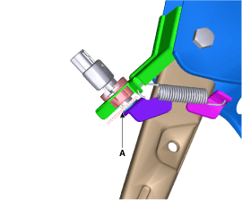
- If the clearance between the brake light switch and the bracket is not 1.0–2.0 mm (0.04–0.08 in.), check the mounting clip and other parts around the brake light switch.
- If everything is normal, remove the stop lamp switch and install it again.
Inspection
1. Check Fuses. Install a test fuse on the brake switch fuse and the relay fuse part to confirm normal operation of the joint.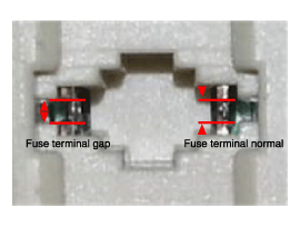
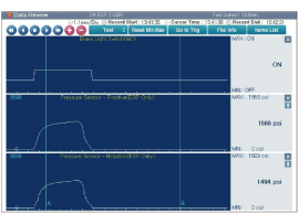
- Analyze the GDS data and confirm that there is a problem with the brake light switch.
- Connect the GDS to the self-diagnosis connector.
- Turn the ignition switch ON.
- Press the brake pedal.
- Inspect the "brake switch" category displayed in the GDS "Sensor Data". Normal signal pattern: the pressure sensor signal value changes according to the brake switch ON/OFF state.
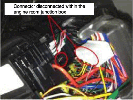
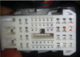
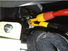
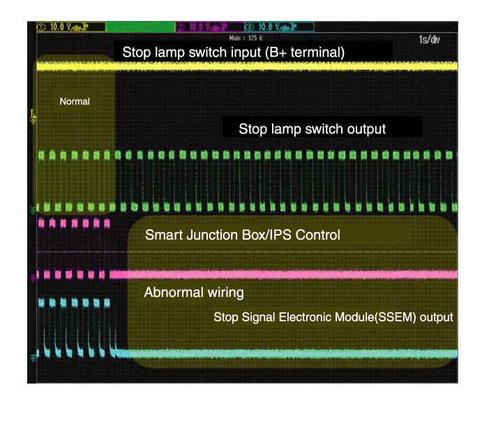
Removal
- Turn the ignition switch OFF and disconnect the negative (-) battery cable.
- Remove the lower under cover. (Refer to Body - Under Cover)
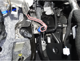
- Disconnect the stop lamp switch connector (A).
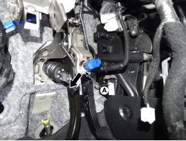
- Pull the lock plate (A) as shown by the arrow.
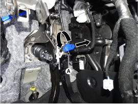
- Turn the brake light switch (A) 45° counterclockwise and remove it.
- Inspect the removed stop lamp switch according to the procedures described below.
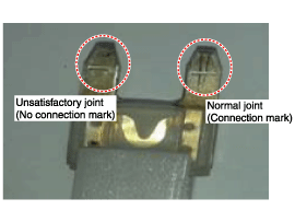
- Confirm normal connection with the terminal part.
- Confirm that the connector is properly secured and that the connection mark is present.
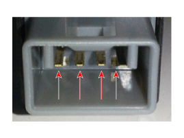
- Perform resistance inspection of the part.
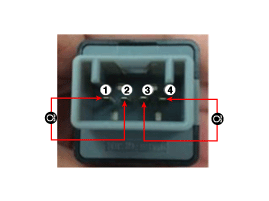
Resistance (Ω) 3-4 1-2 Plunger not protruding
(switch OFF)Infinity 0 Plunger protruding
(switch ON)0 Infinity
- Confirm normal connection with the terminal part.
Installation
- Hold the brake pedal arm and fully insert the brake light switch so that the contact part is hidden.
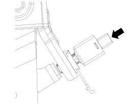
- After inserting, turn the stop switch (A) 45° clockwise, then engage the locking plate by pressing.
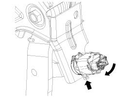
- Check the clearance between the stop lamp switch and the bracket.
Stop lamp switch clearance (A): 1.0-2.0 mm (0.04-0.08 in.)
- Connect the connector of the brake light switch (A).
- Install the lower under cover. (Refer to Body - Under Cover)
Test yourself
A quick Hyundai Kona quiz: every answer comes with an explanation and a link to the manual page.
Was this page helpful?