Be careful not to damage parts located under the vehicle (floor under cover, fuel filter, fuel tank, and canister) when lifting the vehicle with a lift. (Refer to General Information - Jack Lifting Points and Support Points)
Use fender covers to avoid damaging painted surfaces.
To prevent damage, carefully disconnect the wiring connectors while holding the connector housing.
Label all wires and hoses to avoid incorrect connection.
Inspect the timing chain before removing the cylinder head.
Turn the crankshaft pulley damper so that the No. 1 piston is at top dead center (TDC).
Remove the engine assembly from the vehicle. (Refer to Engine and Transaxle Assembly - "Engine and Transaxle Assembly")
Remove the transaxle assembly from the engine assembly. (Refer to Automatic Transaxle System - "Automatic Transaxle")
Remove the drive plate and adapter plate. (Refer to Cylinder Block - "Drive Plate")
Remove the rear oil seal retainer. (Refer to Cylinder Block - "Rear Oil Seal")
Install the engine assembly on an engine stand for disassembly.
Remove the expansion tank. (Refer to Intake and Exhaust System - "Expansion Tank")
Remove the intake manifold. (Refer to Intake and Exhaust Systems — Intake Manifold)
Remove the exhaust manifold. (Refer to Intake and Exhaust System - "Exhaust Manifold")
Remove the timing chain. (Refer to Valve Timing System - Timing Chain)
Remove the water temperature control unit. (Refer to Cooling System - "Water Temperature Control Assembly")
Remove the cylinder head assembly. (Refer to Cylinder Head Assembly - "Cylinder Head")
Remove the lower oil pan and upper oil pan. (Refer to Lubrication System - "Oil Pan")
Remove the oil pump. (Refer to Lubrication System - "Oil Pump")
Remove the oil filter housing. (Refer to Lubrication System - "Oil Filter Housing").
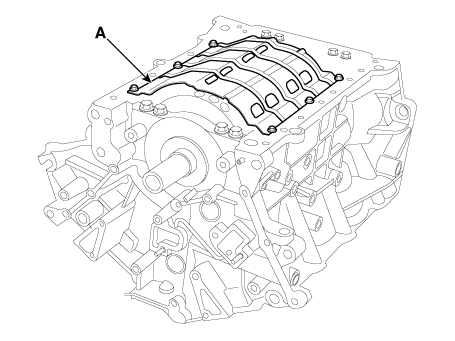
Remove the baffle (A).
Check the connecting rod side clearance. (Refer to Cylinder Block - Piston and Connecting Rod)
Check the connecting rod cap oil clearance. (Refer to Cylinder Block – Piston and Connecting Rod)
Remove the piston and connecting rod assembly. (Refer to Cylinder Block - Piston and Connecting Rod)
Remove the crankshaft main bearing caps and check the oil clearance.
Check the crankshaft end play.
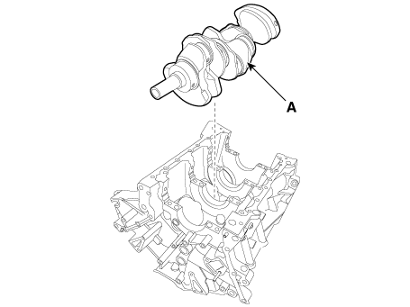
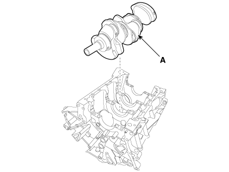
Remove the crankshaft. Lift the crankshaft (A) out of the engine carefully so as not to damage the journals.
Arrange the main bearings and thrust bearings in the correct order.
Inspection
Check the crankshaft bearing oil clearance.
To check the oil clearance between the main bearing and journal, remove the main bearing caps and bearing halves.
Clean each main journal and bearing half with a clean cloth.
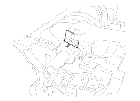
Place one strip of Plastigage on each main journal.
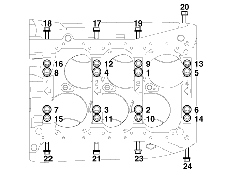
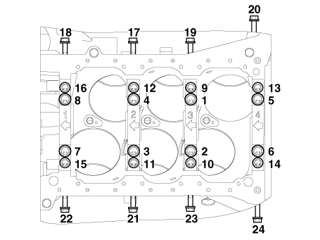
Install the bearings and caps in place and tighten the bolts. Tightening torque: No.1 – 8: 49 N·m + 90° No.9 – 16: 19.6 N·m + 120° No.17 – 24: 29.4 – 31 N·m
Always use new crankshaft main bearing cap bolts. Crankshaft main bearing cap bolts are torque-to-yield bolts designed to be permanently stretched beyond the elastic limit during tightening. If the bolts are removed and reused, they may break or fail to maintain clamping force.
Do not rotate the crankshaft.
Remove the cap and bearing again and measure the widest part of the Plastigage.
Standard oil clearance: 0.023–0.041 mm (0.0009–0.0016 in)
If the Plastigage is too wide or too narrow, remove the upper bearing half, install a new bearing assembly with the same color code (select the color as shown in the following column), and re-check the clearance.
Do not grind, shim, or scratch the bearings or caps to adjust the clearance.
If the Plastigage shows the clearance is still incorrect, try the next larger or smaller bearing (color listed above or below this one) and check the clearance again.
If the proper clearance cannot be obtained by using bearings of the larger or smaller size, replace the crankshaft and start over.
If the marks are illegible due to dirt and dust buildup, clean with solvent or detergent instead of rubbing with a wire brush or scraper.
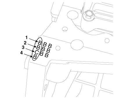
Location of Crankshaft Bore Mark. Letters are stamped on the block as a size code for each of the 4 main bearing bores. Use them, together with the numbers or bar stamped on the crankshaft (main journal size marks), to select the correct bearings.Cylinder Block Identification
Grade
Mark
Inner Diameter
a
A
73.500 - 73.506 mm (2.8937–2.8939 in.)
D
B
73.506 - 73.512 mm (2.8939–2.8942 in.)
c
C
73.512 - 73.518 mm (2.8942–2.8944 in.)
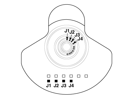
Location of Crankshaft Journal Mark Crankshaft IdentificationCrankshaft Identification
Grade
Mark
Journal Outside Diameter
I
1 or A
68.954 - 68.960 mm (2.7147–2.7150 in.)
II
2 or B
68.948 - 68.954 mm (2.7145–2.7147 in.)
III
3 or C
68.942 - 68.948 mm (2.7142–2.7145 in.)
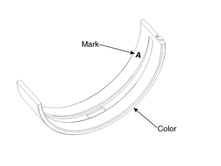
Identification Mark Location (Crankshaft Bearing)Crankshaft Bearing Identification
Grade
Mark
Bearing Thickness
E
Blue
2.276–2.279 mm (0.0896–0.0897 in.)
D
Black
2.273–2.276 mm (0.0895–0.0896 in.)
C
Red
2.270–2.273 mm (0.0894–0.0895 in.)
B
Green
2.267–2.270 mm (0.0893–0.0894 in.)
A
Yellow
2.264–2.267 mm (0.0891–0.0893 in.)
Selection
Crankshaft Bore Identification Mark
A (A)
B (B)
C (C)
Crankshaft Marking
1 or A
A (Yellow)
B (Green)
C (Red)
2 or B
B (Green)
C (Red)
D (Black)
3 or C
C (Red)
D (Black)
E (Blue)
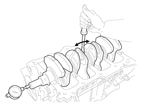
Inspect the crankshaft end play. Using a dial indicator, measure the end play by prying the crankshaft forward and backward with a screwdriver.
Standard end play: 0.10–0.28 mm (0.0039–0.0110 in.)
If the end play is greater than the maximum, replace the thrust bearings as a set.
Thrust bearing thickness: 2.41–2.45 mm (0.0949–0.0964 in.)
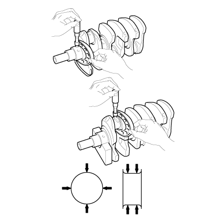
Inspect the main journals and crank pins. Using a micrometer, measure the diameter of each main journal and crank pin. Main journal diameter: 68.942–68.960 mm (2.7142–2.7149 in.) Crank pin diameter: 54.954–54.972 mm (2.1635–2.1642 in.)
Installation
Thoroughly clean all parts to be assembled.
Before installing the parts, apply fresh engine oil to all sliding and rotating surfaces.
Replace all gaskets, O-rings, and oil seals with new parts.
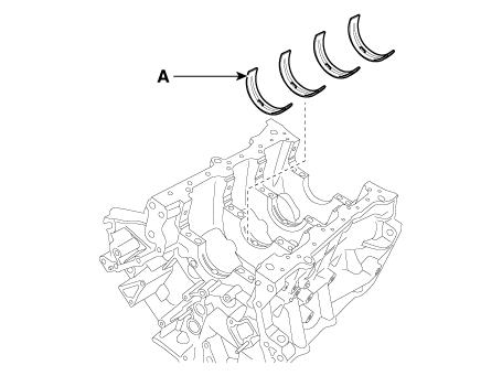
Install the main bearings.
The upper bearings have oil grooves or oil holes, whereas the lower bearings do not.
Align the bearing tab with the tab groove in the cylinder block, and install the 4 upper bearings (A).
Align the bearing tab with the tab groove in the main bearing cap, and install the 4 lower bearings.
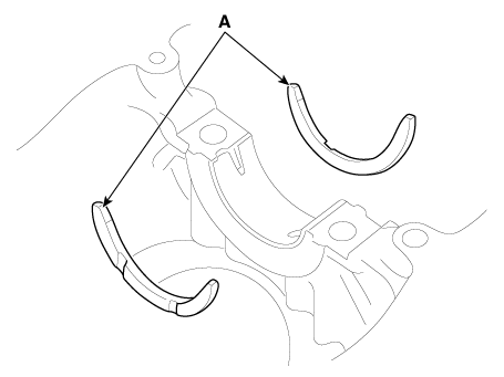
Install the thrust bearings. Install the 2 thrust bearings (A) under the No. 3 journal of the cylinder block with the oil grooves facing outward.
Install the crankshaft (A) on the cylinder block.
Install the main bearing caps on the cylinder block.
Install the main bearing cap bolts.
Install and evenly tighten the bearing cap bolts in several passes in the specified sequence. Tightening torque: Main bearing cap bolts No. 1 - 8: 49 N·m + 90° No. 9 - 16: 19.6 N·m + 120° No. 17 - 24: 29.4 - 31 N·m
Always use new crankshaft main bearing cap bolts. Crankshaft main bearing cap bolts are torque-to-yield bolts designed to be permanently stretched beyond the elastic limit during tightening. If the bolts are removed and reused, they may break or fail to maintain clamping force.
If any bearing cap bolt is broken or deformed, replace it.
Make sure the crankshaft rotates smoothly.
Check the crankshaft end play.
Install the piston and connecting rod assembly. (Refer to Cylinder Block - Piston and Connecting Rod)
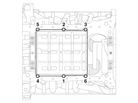
Install the baffle plate. Install and tighten the baffle plate bolts evenly in multiple passes in the sequence shown.
Tightening Torque: 9.8–11.8 N·m
Assemble the remaining components in the reverse order of removal.
After replacing the crankshaft with a new one, select the correct connecting rod bearing according to the mark on the crank pin of the crankshaft.
Connecting Rod Bearing Selection (Refer to Cylinder Block - Piston and Connecting Rod)
?
Test yourself
A quick Hyundai Palisade quiz: every answer comes with an explanation and a link to the manual page.