Advanced Driver Assistance System (ADAS)
Description and Operation
In this manual: Advanced Driver Assistance System (ADAS)
14steps
~84min
3/5difficulty
Done 0 of 14
Description
The Surround View Monitor (SVM) is a system that provides 360-degree video surveillance around the vehicle. The system includes 4 ultra-optical cameras installed around the vehicle (front, both sides, rear). Video from these cameras is processed with distortion compensation, point conversion time and video fusion technology to produce a bird's-eye view image of the vehicle's surroundings, as well as various other viewing modes. The SVM system provides video of the vehicle's surroundings during parking or while driving at low speed to improve driver safety and convenience. In addition, the system displays the video image of the area around the vehicle and includes synchronized guide line indication on the steering wheel, front and rear object warning, and A/S tolerance compensation function (including linear).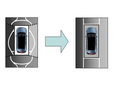
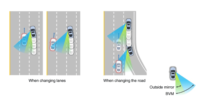
| The BVM system provides the driver with a more complete view that is normally not visible in the side mirrors in certain situations, such as when changing lanes. The system helps to avoid any failures in blind spots. |
- The rear view is displayed on the cluster screen when the turn signal is operated, and the headlights operate when the driver raises and lowers the light switch.
- SVM also provides an adjustable left/right side view without adding additional cameras.
- This helps minimize driver distraction by displaying the rear side view, which is normally difficult to see.
|

Main Specifications
- Display of Vehicles Surrounding the Vehicle. The surround view display function shows a 360-degree video image captured by 4 cameras to the driver through the head unit screen when the vehicle moves at low speed or in reverse. The SVM system displays a total of 8 video modes for displaying the surrounding area based on the vehicle driving state and the driver's selection.
- Guide Line Display and Steering Wheel Synchronization Function. The guide line display and steering wheel synchronization function assists the driver during parking by synchronizing the steering wheel with the rear view video display, marked with a guide line, to help anticipate the vehicle's direction of travel when reversing.
- Front/Rear Object Warning (Obstacle Detection Function). The system receives an obstacle warning signal from the PAS or SPAS sensors installed at the front/rear of the vehicle and displays the obstacle location on the SVM head unit screen.
- Tolerance Compensation (Including A/S). Manual tolerance compensation software is built into the SVMECM to compensate for SVM deviation that may occur due to assembly line tolerance. You must first set up the proper operating environment to perform correct tolerance compensation.
| No | Main Specifications | Detailed Description | Notes |
| 1 | 8 View Mode Display |
|
Combined 8-mode video image |
| 2 | Front Assist Mode Selection Function |
|
Same as the SVM PAS switch |
| 3 | Synchronized Parking Guide Line Display with Rear Steering |
|
Overlay Display on Rear Video |
| 4 | PAS Obstacle Display |
|
Display on both the cluster and the head unit |
| 5 | User Setting Option |
|
Provides additional screen settings |
| 6 | Assembly Line and A/S Tolerance Compensation Function |
|
Compensation function recognition logic applied |
SVM Mode Entry Conditions: Vehicle information is accessed regularly, even after entering SVM mode. When the conditions are met, switching from front mode to rear mode and vice versa is possible. When switching modes, the view displayed on the screen may be the initial view or the previous view depending on the conditions. If the switching mode is the initial entry, the default view based on front or rear is selected. If continuous front-rear switching occurs, as forward and reverse movement is repeated for parking, the previous view is recalled and displayed.
- Initial Entry: when the front or rear view in SVM mode is first displayed on the screen
- Re-entry: When switching from SVM mode to another mode, without turning off SVM, return to the previous mode (e.g., Rear → Front → Rear: re-enter Rear mode / Front → Rear → Front: re-enter Front mode)
| Switching Mode | Vehicle Speed | Mechanism | SVM Switch | Display View |
| Rear → Front | below 20 km/h | R range or P range excluded | ON | Initial Entry: front view is set in the initial view mode option. |
| Re-entry: the last view mode displayed in the previous front mode. | ||||
| Front → Rear | Not applicable | Reverse Gear | Not applicable | Initial Entry: rear view is set in the initial view mode option |
| Re-entry: the last view mode displayed in the previous rear mode. |
SVM Mode Cancellation: If the conditions listed below are met while in SVM mode, SVM is turned off and the video is not displayed.
| OFF mode | Vehicle Speed | Mechanism | SVM Switch | Notes |
| Front mode | more than 20 km/h | R range or P range | OFF | If any one of the three conditions is met |
| Rear mode | Not applicable | Except R gear | Not applicable | If any one of the two conditions is met |
SVM Options: For user convenience, SVM provides three options for the user to select. The option change window (parking assist system settings) is displayed on the AVN. Only changed options are sent to the SVM unit via M_CAN. These three options are applied as soon as they are selected by the user. Depending on the conditions, the initial displayed views are as follows.
| Option | Function | Default settings |
| Steering Lock | Steering lock guide lines to show the vehicle's direction of travel during parking. | Classification code |
| Close Distance Warning Indicator | Indicates obstacle detection at the front and rear | Classification code |
| Initial View Mode Setting | Default view displayed when entering SVM mode | Front view + surround view |
| Rear + surround view |
Operation for Steering Lock Guide Line Display. The steering lock guide line display uses the steering wheel angle value periodically received by the SVM unit over the C-CAN bus. The rear area, which displays the 130-degree rear view image (two-section mode) and the wide view, is displayed with the expected vehicle travel path.
- View Modes for Steering Lock Guide Display
Mode View Notes Rear Rear wide view + surround view 
Rear top view + surround view 
Rear corner view + bird's-eye view 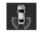
- Steering Lock Guide Line Specifications
Number Range Color ① 0.5 m Red ② 1 m Yellow ③ 3 m Yellow ④ Left edge of bumper + 0.3 m Yellow ⑤ Right edge of bumper + 0.3 m Yellow
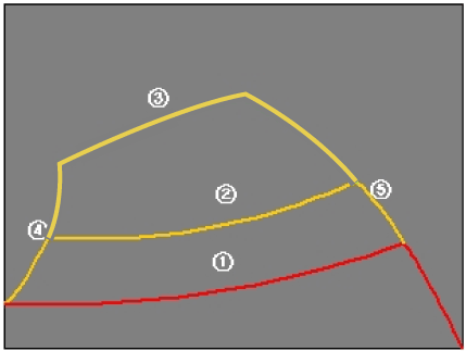
- Neutral Trace Line Indications: If the steering wheel angle is neutral, the neutral trace line is displayed in blue, which shows the expected movement path of the vehicle. This line is displayed together with the steering-lock guide line and a fixed line that is not linked to the steering wheel angle operation.
- Camera Input
Category Specification Lens Viewing Angle 190° Viewing Angle Horizontal 186° Vertical 135° Provided Function Provides original wide-angle image (No additional functions) Operating Position Applies to front/rear/left/right cameras - SVM Image Display: Images received from the four cameras installed on the vehicle pass through the image distortion correction logic and the image merging process. The H/UNIT displays these images together with other additional functions, such as parking guidelines linked to the steering wheel, on the AVN screen.
- Park/View Button: It is used as a control input signal for operating the front view mode. Operates with the ignition switched on.
- Ignition Input: The SVM unit displays the image only when IGN2 is on, and restricts image display with the SVM off when IGN2 is off. The SVM unit uses the signal received at the IGN terminal or the M-CAN message routed from the IGPM (gateway) to the C-CAN to determine IGN2 on/off status.
- Switch Indicator Display: The SVM unit displays the LED power inside the SVM switch as a PWM wave to inform the user whether the SVM switch is pressed.
- Chassis CAN Input (C_CAN): The SVM unit receives vehicle status information through the C_CAN to determine the operation of the main SVM functions.
- Multimedia CAN Input/Output: Related information is processed by receiving the M-CAN signal routed from the IGPM (gateway) to the C-CAN. The routed M-CAN signal communication is used to transmit and receive the information below.
Test yourself
A quick Hyundai Palisade quiz: every answer comes with an explanation and a link to the manual page.
Was this page helpful?