Automatic Transmission System (A8LF1)
Position Sensor
In this manual: Automatic Transmission System (A8LF1)
18steps
~108min
4/5difficulty
Done 0 of 18
Specifications
Specification
| Item | Specification | |
| Supply voltage (V) | 4.5 - 5.5 V | |
| Output type | Shift range | Non-contact (2-channel PWM signal) |
Description and Operation
Description
Shift position output signal (P, R, N, D) from the actuator to the controller (SBW_SCU Control Unit).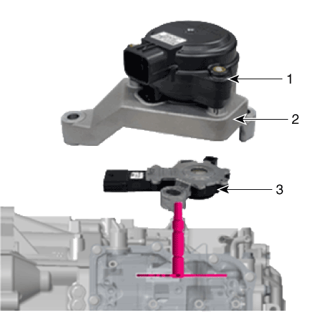
| 1. Electronic shift actuator 2. Bracket 3. Position sensors |
Troubleshooting
Troubleshooting
| Main Symptom | Possible Cause | Components to Inspect and Remedy |
| Shock when shifting into D/R and back Engine races when shifting into D/R |
Incorrect "N" position sensor adjustment | Use the "N" adjustment tool and adjust the "N" setting. (Refer to "Automatic Transmission System - Position Sensor") |
| Incorrect hydraulic control unit oil pressure | Replace the valve body assembly or inspect/replace the transaxle assembly. | |
| Engine starts improperly Current gear not shown in cluster Warning lamp ON Engine stalls when stopping Creep function not possible Automatic parking release disabled |
Faulty CAN termination resistor/circuit | Check the TCM / battery management system module. |
| Check the TCM wiring connector connection. | ||
| Position sensor circuit fuse is faulty | Check the fuse and the junction box terminal and repair. | |
| Faulty position sensor wiring connector | Check for foreign material in the wiring connector and check the terminals for play. | |
| Check the seal on the unused pin and make sure there is no corrosion on the terminal. | ||
| Faulty reverse lamp circuit | Check the reverse lamp ground and reassemble if necessary. | |
| Faulty position sensor wiring ground |
Check the wiring ground and reassemble if necessary. | |
| Position sensor DTC | Inspect according to the inspection procedure, then replace the position sensor if necessary. |
Repair Procedures
Removal
|

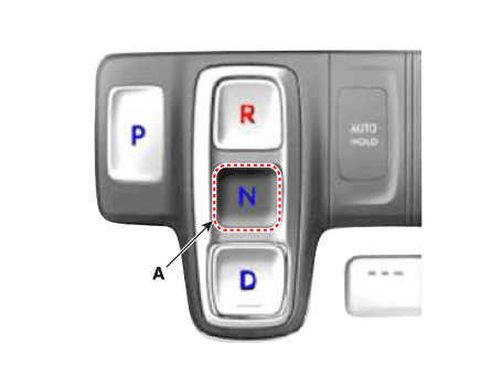
- Turn the ignition switch OFF and disconnect the negative (-) battery cable.
- Remove the battery and battery tray. (Refer to Engine Electrical System - "Battery")
- Remove the air duct and air cleaner assembly. (Refer to Engine Mechanical System - "Air Cleaner")
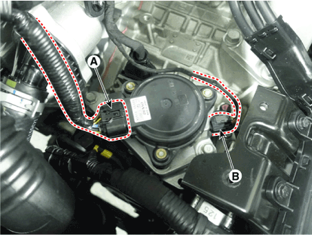
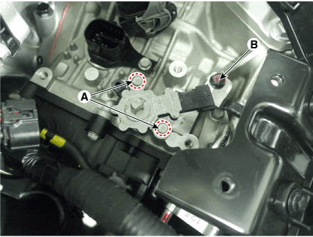
- Disconnect the position sensor connector (A).
- Disconnect the electronic shift actuator connector (B).
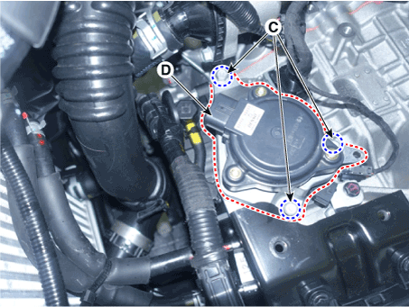
- Remove the electronic shift actuator (D) by removing the bolts (C).
- Remove the position sensor (B) after removing the bolts (A).
Installation
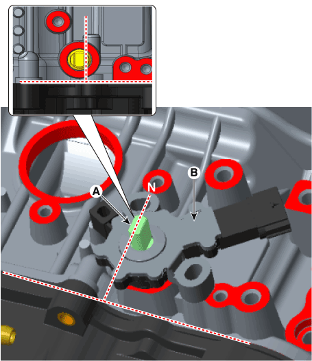
- Make sure the shaft (A) is in the "N" position.
- Install the position sensor (B).
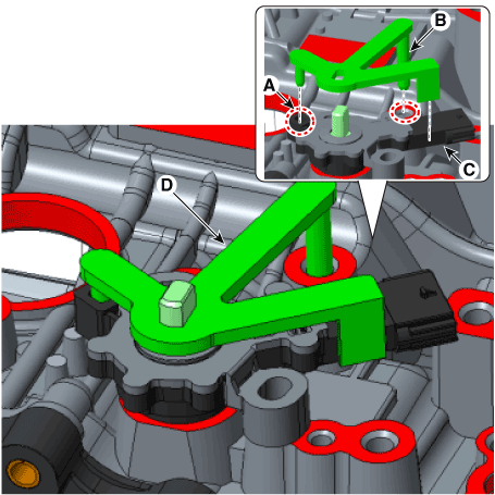
- Install the "N" position sensor fixing SST (No.: 09459 - 4G100) (D) into the sensor (A), housing pin (B) and anti-rotation guide (C).
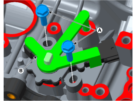
- Install the bolts (A) into the position sensor.
Tightening Torque: 9.8–11.8 N·m
- Remove the "N" position sensor fixing SST (No.: 09459 - 4G100) (B).
- Install the electronic shift actuator (A).
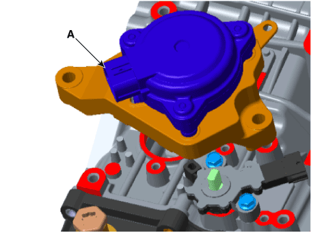
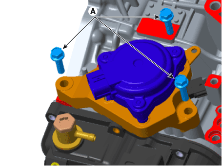
- Install the bolts (A).
Tightening torque: 20.6–26 N·m
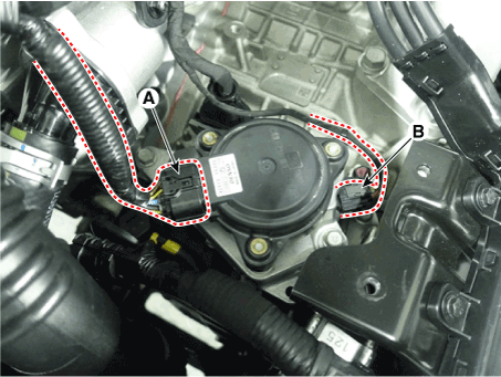
- Connect the electronic shift actuator (A) and the position sensor (B).
- Install the air duct and air filter assembly. (Refer to Engine Mechanical System - "Air Filter")
- Install the battery and battery tray. (Refer to Engine Electrical System - "Battery".)
- Make sure that the position sensor operates smoothly in each range corresponding to each position of the electronic shift button.
Test yourself
A quick Hyundai Palisade quiz: every answer comes with an explanation and a link to the manual page.
Was this page helpful?