In this manual: Heating, Ventilation and Air Conditioning
43steps
~263min
5/5difficulty
1special tools
Tightening torque found on this page
Done 0 of 43
Description and Operation
Description
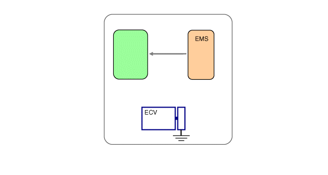
The compressor is the power unit of the air conditioning system. It is mounted on the side of the cylinder block and driven by the engine drive belt. The compressor converts low-pressure, low-temperature refrigerant gas into high-pressure, high-temperature refrigerant gas. Variable displacement swash plate compressor: the compressor has a swash plate that rotates together with the pistons that compress the refrigerant. The variable displacement swash plate compressor changes the swash plate angle to vary the refrigerant volume. It precisely controls cooling capacity according to cabin and driving conditions. The externally controlled variable displacement compressor changes the swash plate angle using the ECV (electronic control valve) according to electrical signals from the heating and air conditioning control unit. This helps maintain stable temperature control and improves driving feel. ECV control circuit
Components and Component Location
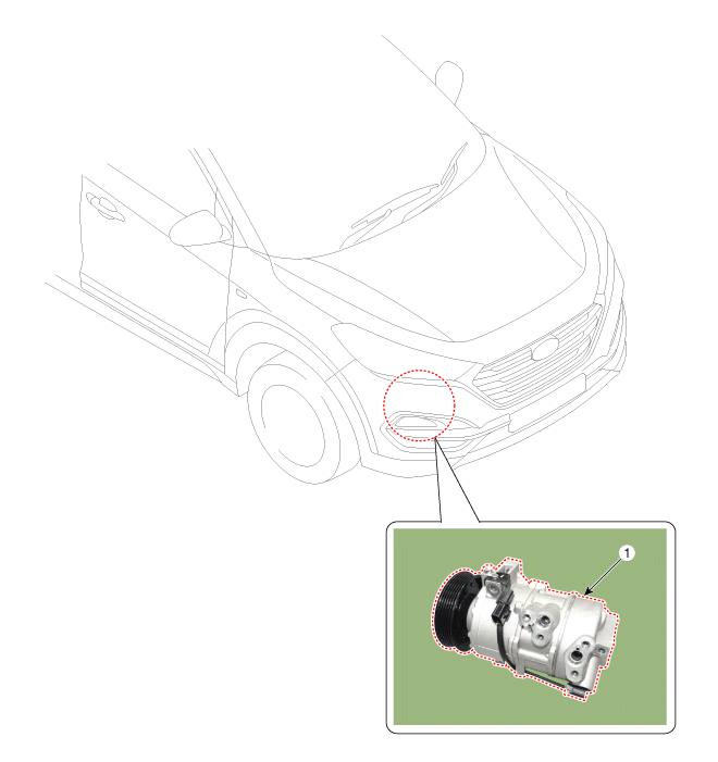
Component location
1. Compressor
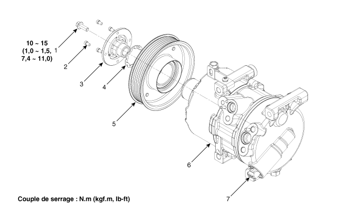
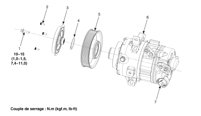
COMPONENTS
[Gamma Engine]
1. Clutch bolt 2. Stopper bolt 3. Hub and stopper assembly 4. Elastic ring
5. Pulley 6. Compressor 7. Electronic control valve (ECV)
[Bare Engine]
1. Clutch bolt 2. Stopper bolt 3. Hub and stopper assembly 4. Elastic ring
5. Pulley 6. Compressor 7. Electronic control valve (ECV)
Repair Procedures
DEPOSIT
If compressor operation is difficult, start the engine and run it at idle, activate the air conditioning for several minutes, then turn off the engine.
Disconnect the negative (-) battery terminal.
Recover the refrigerant using a refrigerant recovery/recharge system.
Remove the under cover. (Refer to Engine Mechanical System - "Engine Room Cover")
Loosen the drive belt. (Refer to Engine Mechanical System - "Drive Belt")
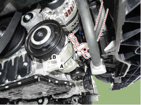
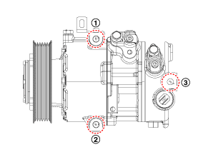
Remove the bolts and disconnect the suction line (A) and discharge line (B) from the compressor.
Tightening torque: 8.8 - 13.7 N·m
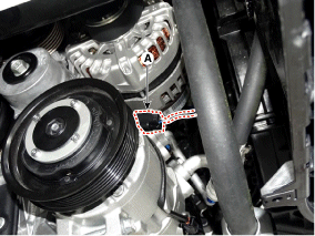
Disconnect the compressor switch connector (A).
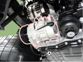
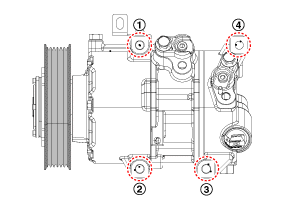
Remove the compressor (A) by loosening the mounting bolts.
To install, perform the removal procedure in reverse order.
Inspection
Inspect the metal parts of the limiter and hub for discoloration, chips, or other damage. If damaged, replace all of them.
Check the pulley bearing (A) for play and rotational friction by turning the pulley by hand. If abnormal noise, play, or excessive resistance is found, replace the pulley with a new one.
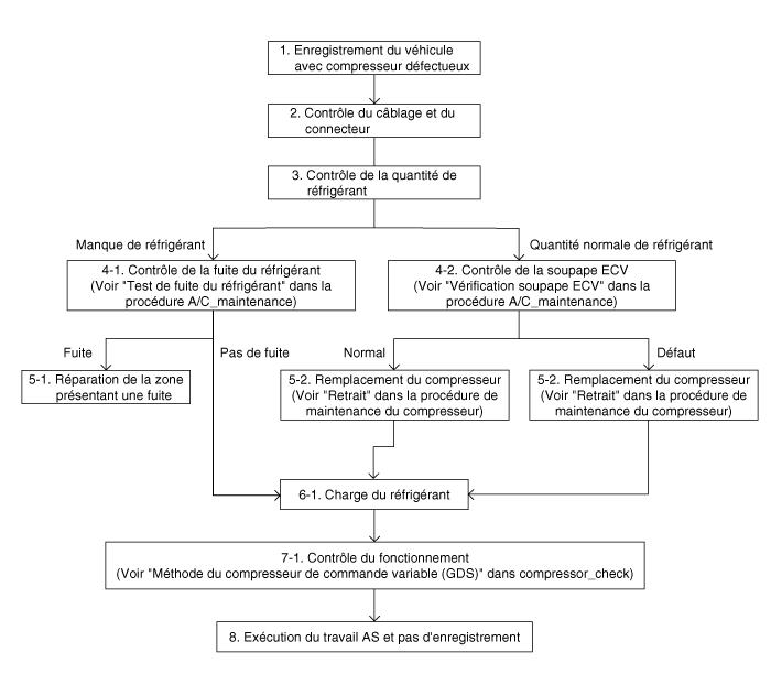
Compressor Diagnostic Flow Chart
Check
[ECV Valve Check]
The ECV valve check is a method to determine whether the compressor is faulty due to a failure of the ECV valve or not. When a compressor malfunction is detected, disconnect the ECV valve connector and activate the ECV valve with battery voltage to check whether the A/C pressure is high or not.
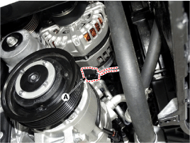
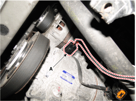
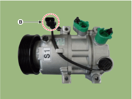
Disconnect the ECV valve connector (A) by pressing the stopper pin.
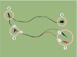
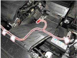
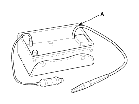
Install the ECV valve check kit.Check the kit components: Mobis P/N: 00305 CONFIRMATION (1) Alligator clips for battery connection (2) Fuse (3) Power switch (4) ECV valve connector
Connect the ECV valve connector (A) from the kit to the ECV valve connector (B) on the compressor.
Connect the test kit to the battery terminals. Red alligator clip: connect to the battery positive (+) terminal. Black alligator clip: connect to the battery negative (-) terminal.
Connect the GDS diagnostic tester to the vehicle's diagnostic connector.
Turn the ignition switch ON.
Select 'Vehicle Type' and 'Engine System', then confirm.
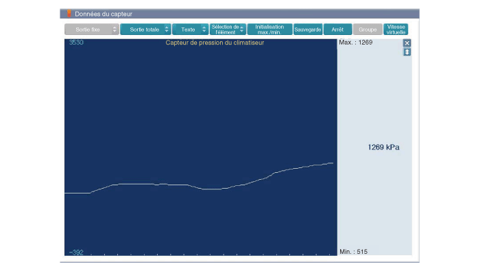
Select the 'A/C Pressure' value in the sensor data analysis menu.
Turn the ignition switch ON.
Activate the control kit switch.
Check the 'A/C Pressure' value in the 'Sensor Data Analysis' menu in GDS. Normal A/C pressure value: Above 1000 kPa when the control kit switch is activated is normal.
Turn the ignition off.
Remove the alligator clips from the battery terminals of the control kit.
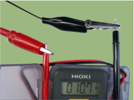
Measure the resistance between the alligator clips of the battery in the test kit.
Standard resistance: 10.1 ~ 11.1 Ω (25 °C)
[Compressor External Control Valve Check (GDS)]
Compressor type: fixed displacement compressor, external control valve, internal control valve. For a fixed type and internal control valve, the compressor operation can be checked by the clutch engagement noise. However, if it is an external control valve, it cannot be controlled in this way because it has no clutch. Therefore, the ECV should be checked using GDS as follows.
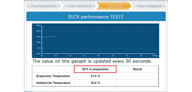
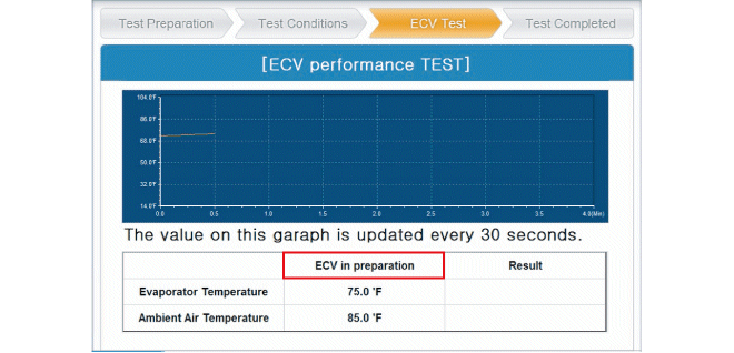
Connect GDS to the vehicle and select "A/C Compressor Check (ECV type)". [ECV1]
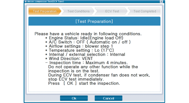
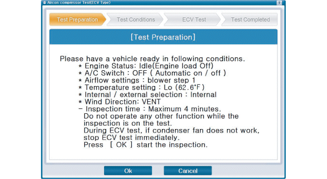
Prepare the vehicle according to the GDS instructions on the monitor (only turn off the A/C switch). [ECV2] [ECV3]
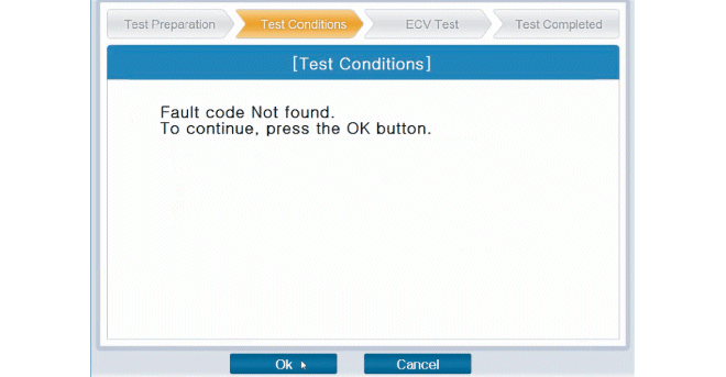
Before checking the compressor, check whether any other ECV DTCs are present. If so, troubleshoot them first. Otherwise, press the "OK" button to continue. [ECV4]
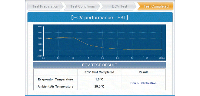
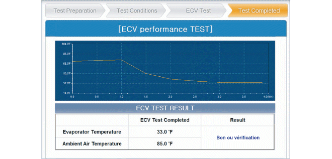
Start the inspection [ECV5] [ECV6]
Check the inspection result and press "Detailed Inspection". If "Noted", follow the instructions and recheck the ECV, restarting from the first step. [ECV7] [ECV8]
[REFRIGERANT LEAK CHECK]
Always perform a refrigerant leak test with an electronic leak detector when a leak is suspected, and during service operations involving disassembly or loosening of fittings.If a refrigerant leak is detected, perform the following steps:
Check the torque of the connections and, if loose, tighten to the specified torque. Check for gas leaks using a leak detector (A).
If the leak persists after tightening the fittings, evacuate the refrigerant from the system, disconnect the fittings, and inspect their sealing surfaces for damage. Always replace, even if the damage is minor.
Check the oil level in the compressor and add more if necessary.
Charge the system and recheck for gas leaks. If there are no leaks, evacuate and recharge the system again.
DISASSEMBLY
[Compressor Assembly]
Remove the front wheel arch. (Refer to Body - Front Fender)
Loosen the drive belt. (Refer to Engine Mechanical System - "Drive Belt")
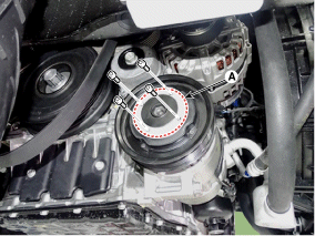
Remove the clutch bolt (A) while holding the pulley with the clutch bolt puller (09977-25100).
Tightening torque: 10.0 ~ 15 N·m
Loosen the limiter bolts and remove the hub assembly and limiter.
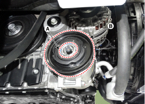
Remove the pulley (B) after removing the snap ring (A) with snap ring pliers.
For reassembly, perform the removal procedure in reverse order.
Clean the sliding surfaces of the pulley and compressor with an oil-free solvent.
Install a new snap ring and make sure it is properly seated in the groove.
Make sure the pulley rotates smoothly after assembly.
[ECV Valve]
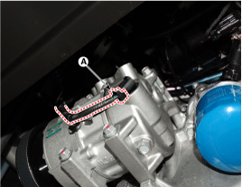
Disconnect the compressor ECV connector (A) by pressing the stopper pin.
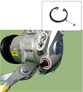
Remove the snap ring (A) attached to the ECV using pliers.
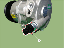
Remove the ECV (A) in the direction indicated by the arrow.
Installation is the reverse of removal.
?
Test yourself
A quick Hyundai Tucson quiz: every answer comes with an explanation and a link to the manual page.