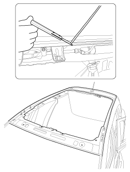
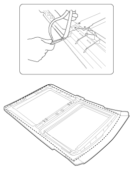
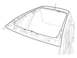
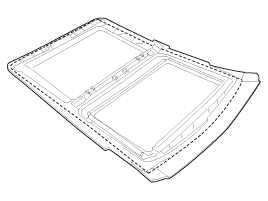
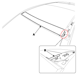
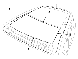
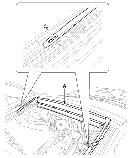
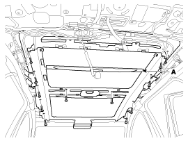
Loosen the retaining screws and remove the glass (A).
Do not damage the screw.
Install in the reverse order of removal.
Remove the headliner. (Refer to Interior - "Headliner")
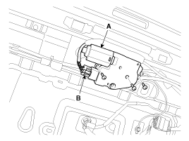
Disconnect the connector (B).
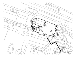
Remove the panoramic roof motor after removing the motor screws (A).
Install in the reverse order of removal.
Be sure to initialize the motor.
Fully open the glass.
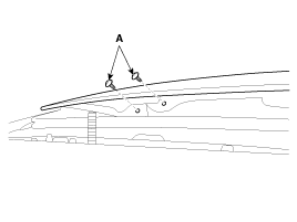
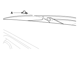
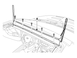
Using a star wrench, loosen the wind deflector retaining screw (A).
Do not damage the screw.
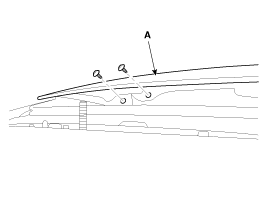
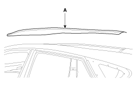
Loosen the retaining screws and remove the wind deflector (A).
Install in the reverse order of removal.
Motor Replacement Wind Deflector Replacement Sunshade Replacement
Removal
Remove the glass.
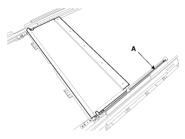
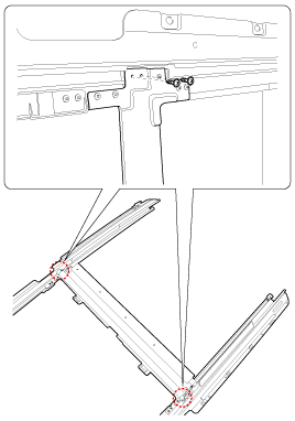
Remove the mechanism guide assembly by loosening the retaining screw, then remove the mechanism guide assembly (A).
Do not damage the screw.
Cut the tension wire (A) to prevent injury.
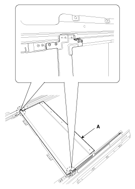
Loosen the sunshade retaining screws and remove the rivet, then remove the sunshade (A).
Do not damage the screw.
Installation
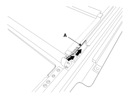
Install the sunshade (A).
Insert the fabric portion into the guide at both ends.
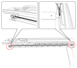
Install the wire (A) in the direction of the arrow.
Install the wire (B) in the direction of the arrow.
Fully insert the wire into the cover during installation.
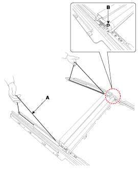
Pull the wire (A) as shown in the illustration below.
Slowly lower the wire (A) after removing the clip (B).
Sunshade coherence specification: 6.9–26 N·m
Front Fixed Glass Replacement
Removal
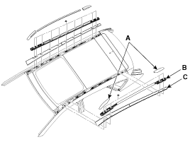
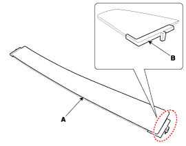
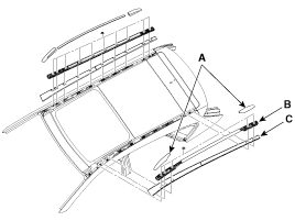
Using a screwdriver or a pry tool, remove the roof rack cover (A).
Loosen the retaining nuts and remove the roof rack (B).
Using a screwdriver or a pry tool, remove the molding (C).
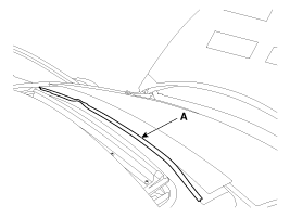
Disconnect the front fixed glass seal (A).
Replace the damaged front fixed glass seal.
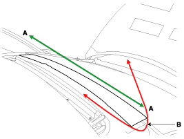
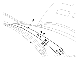
Cut the sealant at the side (A-A) by pulling the wire (B) of the front fixed glass.
Wear gloves to protect your hands.
Heat may be generated when working with the wires. Be careful not to burn your hands.
Be careful not to disconnect the wire.
When using a flat-blade screwdriver, wrap it with protective tape and apply protective tape around the corresponding parts to prevent damage.
Be careful not to scratch the body surface.
Two or more people are required to pull the wire.
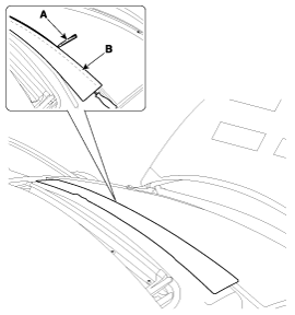
Open the gap between the body and the front fixed glass using a flat-blade screwdriver, then cut the sealant (B) from the edge using a utility knife (A).
Remove the front fixed glass (A).
Installation
Do not reuse the fixed glass.
Using a knife, scrape off the old adhesive to a thickness of approximately 2 mm (0.08 in) on the bonding surface around the entire panoramic roof flange:
A.
Do not scrape down to the painted body surface; damaged paint will interfere with proper bonding.
B.
Remove the grommet and clips from the body.
C.
Mask the surrounding surfaces before painting.
Using a sponge, apply a thin coat of body primer over the original adhesive remaining around the windshield opening flange. Allow the body primer to dry for at least 10 minutes:
A.
Do not apply glass primer to the body. Be careful not to mix up the glass primer and body primer sponges.
B.
Never touch primed surfaces with your hands.
C.
Mask the instrument panel before painting the flange.
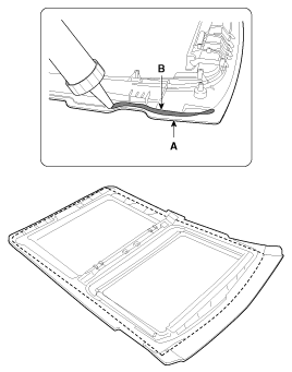
Pack the adhesive into the cartridge without air pockets to ensure continuous delivery. Place the cartridge in the sealant gun and run a sealant bead (B) along the edge of the panoramic roof frame as shown. Apply the adhesive within 30 minutes after applying the primer. Make the bead slightly thicker at each corner.
Insert the SST (09816-2S100) (B) between the fixed glass and each side of the panel to install the fixed glass (A), as shown in the illustration below.
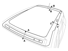
After installing the panoramic roof, check the gap and flush on each side.
Section
Gap
Sale
Front Edge
A-A
5 mm (0.1969 in)
0 mm
Rear Edge
B-B
7 mm (0.2756 in)
1.2 mm (0.0472 in)
Side edge
C-C
0 mm
0 mm
Install the roof molding (C).
Install the roof rack (B) and the roof rack cover (A).
Panoramic Roof Assembly Replacement
Removal
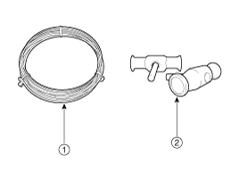
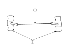
To remove the sunroof assembly, use the tools shown in the following illustration: [Tool Illustration]Piano WireInsert-Type Wire Retainer [Tool Assembly Illustration]
Insert and secure the piano wireinto the wire retainer insertion hole .
Remove the following components:
A.
Front Seat (Refer to Seat and Power Seat - "Front Seat")
B.
Rear Seat (Refer to Seat and Power Seat - "Rear Seat")
C.
Interior Trim (Refer to Interior - "Interior Trim")
D.
Roof Trim (Refer to Interior - "Roof Trim")
E.
Roof Rack and Roof Molding (Refer to Exterior - "Body Side Moldings")
F.
Front Fixed Glass
To protect the interior, cover the interior before removing the sunroof.
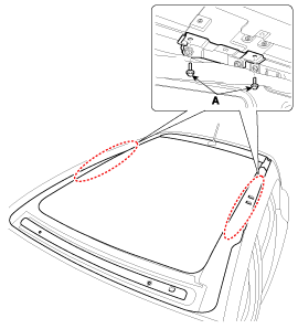
Remove the sunroof panel mounting bracket (A) by loosening the mounting bolts.
Tightening torque: 19.6 - 29 N·m
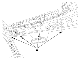
Remove the sunroof mounting nuts (A).
Tightening torque: 19.6 - 29 N·m
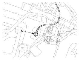
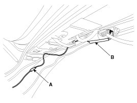
Disconnect the ground wire (A) by removing the bolt.
Tightening torque: 10.8 ~ 13.7 N·m
Disconnect the connector (A) and the wiring harness (B).
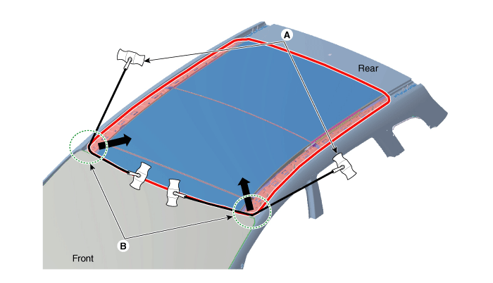
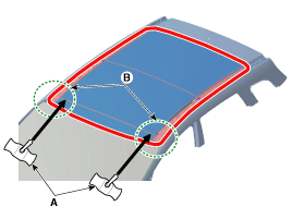
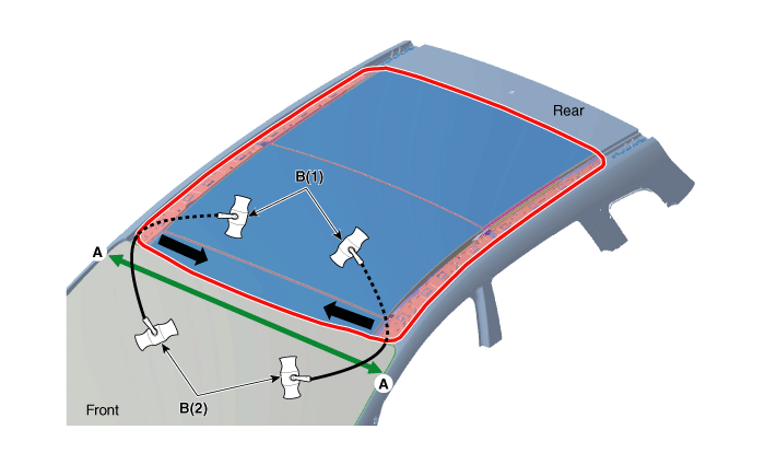
Pull the square wire (A) to the left and right, then pull in the direction of the arrow to cut the remaining sealant on the front edge (B).
Make sure to wear gloves to protect your hands from possible injury.
Be careful not to burn your hands from the heat generated by the wire.
Be careful when working with the wiring harness, as it may be cut.
Be careful not to damage the body.
Make sure that two or more people work together when using the wire.
Push the wire (A) from the outside of the housing toward the face of the edge (B) in the direction indicated by the arrow.
When the wire is visible inside the body, pull the wire (A) inward.
Pull the square wire (B) to the left and right, then pull in the direction of the arrow to cut the remaining sealant on the front section (A-A).
A.
B(1): Work inside the vehicle
B.
B(2): Work outside the vehicle
Make sure to wear gloves to protect your hands from possible injury.
Be careful not to burn your hands from the heat generated by the wire.
Be careful when working with the wiring harness, as it may be cut.
Be careful not to damage the body.
Make sure that two or more people work together when using the wire.
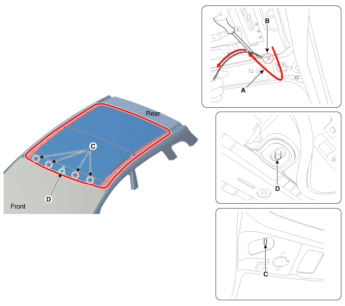
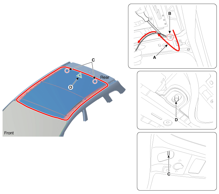
When using the wire to remove the sealant, interference may occur between the nut hole and the device hole. In this case, remove the sealant as shown in the following illustration:Use a scraper or a flat-tip screwdriver to pry up the area between the body and the sunroof.Turn and pull out the wire (A) between the nut hole and the device hole (B) in the direction indicated by the arrow. Then cut off the remaining sealant again.
Be careful not to damage the nut hole (C).
Be careful not to damage the device hole (D).
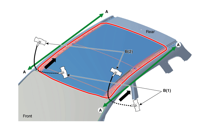
Pull the square wire (B) to the left and right, then pull in the direction of the arrow to cut the remaining sealant on the side section (A-A).
A.
B(1): Work inside the vehicle
B.
B(2): Work outside the vehicle
Make sure to wear gloves to protect your hands from possible injury.
Be careful not to burn your hands from the heat generated by the wire.
Be careful when working with the wiring harness, as it may be cut.
Be careful not to damage the body.
Make sure that two or more people work together when using the wire.
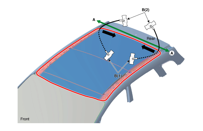
Pull the square wire (B) to the left and right, then pull in the direction of the arrow to cut the remaining sealant on the rear section (A-A).
A.
B(1): Work inside the vehicle
B.
B(2): Work outside the vehicle
Make sure to wear gloves to protect your hands from possible injury.
Be careful not to burn your hands from the heat generated by the wire.
Be careful when working with the wiring harness, as it may be cut.
Be careful not to damage the body.
Make sure that two or more people work together when using the wire.
When using the wire to remove the sealant, interference may occur between the nut hole and the device hole. In this case, remove the sealant as shown in the following illustration:Use a scraper or a flat-tip screwdriver to pry up the area between the body and the sunroof.Turn and pull out the wire (A) between the nut hole and the device hole (B) in the direction indicated by the arrow. Then cut off the remaining sealant again.
Be careful not to damage the nut hole (C).
Be careful not to damage the device hole (D).
Cut the tape between the sunroof and the body. Remove the sunroof (A).
An assistant is required when removing and installing the sunroof.
Installation
To install the sunroof assembly, use the tools shown in the following illustration: [Tool Illustration]Sealant NozzleAutomotive Glass SealantSealant Gun
Using a knife, scrape off the old adhesive to a thickness of approximately 2 mm (0.08 in.) on the bonding surface around the entire sunroof opening flange.
Do not scrape down to the painted body surface; damaged paint will interfere with proper bonding.
Remove the grommet and clips from the body.
Mask the surrounding surfaces before painting.
Clean the body bonding surface with a sponge moistened with alcohol. After cleaning, make sure that oil, grease, and water do not contaminate the clean surface.
Using a sponge, apply a thin coat of body primer over the original adhesive remaining around the windshield opening flange. Allow the body primer to dry for at least 10 minutes:
A.
Do not apply glass primer to the body. Be careful not to mix up the glass primer and body primer sponges.
B.
Never touch primed surfaces with your hands.
C.
Mask the instrument panel before painting the flange.
Apply a thin layer of glass primer to the outer side of the fasteners.
A.
Never touch the primed surface with your hands. If you do, the adhesive may not bond properly to the glass, causing a leak after the windshield is installed.
B.
Do not apply body primer to the glass.
C.
Keep water, dust, and abrasive materials off the primer.
Pack the adhesive into the cartridge without air pockets to ensure continuous delivery. Place the cartridge in the sealant gun and apply a bead of sealant (B) along the edge of the sunroof (A), as shown in the illustration. Apply the adhesive within 30 minutes after applying the glass primer. Make the bead slightly thicker at each corner.
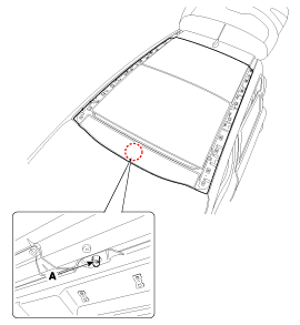
When installing the sunroof, align the body centering device hole (A) and place the sunroof on the body flange. [Front][Rear]
After installing the sunroof, check the alignment and clearance on each side.
X
Section
Alignment
Gap
Front
A-A
0 ± 1 mm
5 ± 1 mm
(0 ± 0.0394 in.)
(0.1969 ± 0.0394 in.)
Rear
B-B
0.7 ± 1 mm
5 ± 1 mm
(0.0276 ± 0.0394 in.)
(0.1969 ± 0.0394 in.)
Side
C-C
-
5 ± 1 mm
(0.1969 ± 0.0394 in.)
Install the sunroof mounting nuts (A).
Tightening torque: 19.6 - 29 N·m
Install the bolts (A) to the sunroof panel mounting bracket.
Tightening torque: 19.6 - 29 N·m
Insert the SST (09816-2S100) (B) between the fixed glass and the panel side to install the fixed glass (A), as shown in the illustration below.
Scrape or wipe off excess adhesive with a spatula or a clean towel. To remove adhesive from painted surfaces or the windshield, wipe with a soft cloth moistened with alcohol.
Allow the adhesive to dry for at least one hour, then spray water over the roof and check for leaks. If a leak occurs, allow it to dry, then seal with sealant:
A.
Allow the vehicle to stand for at least four hours after windshield installation. If the vehicle must be driven within 4 hours, drive it slowly.
B.
Keep the windshield dry for the first hour after installation.
Install all remaining removed parts. Install the rear view mirror after the adhesive has fully dried. Advise the customer not to do the following things for two to three days:
A.
Close doors gently and raise all windows.
B.
Excessive body twisting (for example, when driving onto or off of an angled road surface or over uneven roads).
Install the following parts.
A.
Front Seat (Refer to Seat and Power Seat - "Front Seat")
B.
Rear Seat (Refer to Seat and Power Seat - "Rear Seat")
C.
Interior Trim (Refer to Interior - "Interior Trim")
D.
Roof Trim (Refer to Interior - "Roof Trim")
E.
Roof Rack and Roof Molding (Refer to Exterior - "Body Side Moldings")
Adjustment
Glass Alignment Inspection
Check for abnormal noise or binding during operation.
With the sunroof fully closed, check for water leaks.
The roof panel (A) must be flush with the glass (B) seal, within the standard value "E" around the entire perimeter. If not, perform the following adjustment. Standard value "E" [mm (in.)] Front edge: 1.2 mm (0.0472 in.) Rear edge: 1.0 mm (0.0394 in.)
If the position is not as specified, slightly loosen the glass adjusting screws (A) to adjust the glass height, then tighten them.
Turn the ignition switch to ON and fully close the panoramic sunroof.
Release the sunroof control lever by pressing the switch.
Press and hold the CLOSE button for more than 10 seconds until the sunroof moves slightly.
Release the sunroof control lever.
Press and hold the CLOSE button again until the sunroof does the following.
A.
Tilt > Slide Open > Slide Close, then release the switch.
The panoramic roof reset procedure is complete.
At the time of manufacture.
If the initial setting is erased due to loss of power.
After using the manual handle.
Use the sunroof emergency handle to close and open the sunroof manually only in the following case.
A.
To close the sunroof before driving the vehicle in rainy weather during the day or on the highway, if the sunroof cannot be closed due to a failure of the engine or the sunroof controller.
Operation Method
A.
Remove the overhead console
B.
Insert the emergency handle upward into the hexagonal drive of the sunroof motor. Push firmly enough to disengage the motor clutch; otherwise the emergency handle will slip out due to incomplete engagement with the motor.
C.
Carefully turn the emergency handle clockwise to close the sunroof.
D.
After closing the panoramic roof, turn the handle back and forth when you remove the tool from the motor to make sure that the motor coupling re-engages.
E.
Instead of the emergency handle, you can use a 5 mm hex head with a speeder-type handle.
Do not use power tools to operate the panoramic roof. Damage to components may occur.
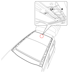
How to Initialize the Motor: Whenever the battery is disconnected, discharged, or the related fuse is replaced or reinstalled, the panoramic roof system must be reset using the procedure below. When to Initialize the Motor. Panoramic Roof Emergency Handle Operation
?
Test yourself
A quick Hyundai Tucson LM quiz: every answer comes with an explanation and a link to the manual page.



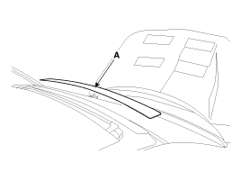
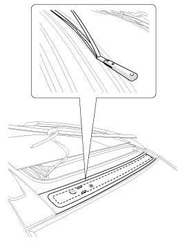
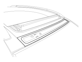
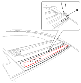
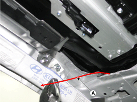
 Use a scraper or a flat-tip screwdriver to pry up the area between the body and the sunroof.
 Turn and pull out the wire (A) between the nut hole and the device hole (B) in the direction indicated by the arrow. Then cut off the remaining sealant again.
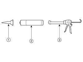
 Sealant Gun