Subthrottle Sensor Output Voltage Inspection
- Measure the output voltage at the subthrottle sensor in the same way as input voltage inspection, note the following.
Disconnect the subthrottle sensor connector and connect the setting adapter [A] between these connectors.
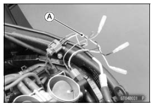
Special Tool - Throttle Sensor Setting Adapter: 57001 -1538
Subthrottle Sensor Output Voltage Connections to Adapter: Digital Meter (+) → R (sensor BL/W) lead Digital Meter (–) → BK (sensor BR/BK) lead
- Disconnect the subthrottle valve actuator connector [A].

- Measure the output voltage with the engine stopped with the connector joined.
- Connect the following parts to harness connectors temporarily.
Output Voltage Standard: DC 0.8  1.0 V at
subthrottle valve full close position (for reference) DC 4.28  4.32 V at subthrottle valve
full open position
NOTE
- Open the subthrottle valves, confirm the output voltage will be raise.
- The standard voltage refers to the value when the voltage reading at the Input Voltage Inspection shows 5 V exactly.
- When the input voltage reading shows other than 5 V, derive a voltage range as follows. Example: In the case of a input voltage of 4.75 V.
If the reading is out of the standard, check the subthrottle sensor resistance (see Subthrottle Sensor Resistance Inspection).
If the reading is within the standard, remove the ECU and check the wiring for continuity between harness connectors.
Special Tool - Hand Tester: 57001-1394
Disconnect the ECU and sensor connectors.
Wiring Continuity Inspection ECU Connector [A] ←→ Subthrottle Sensor Connector [B] BL/W lead (ECU terminal 12) [C] BR/BK lead (ECU terminal 13) [D]
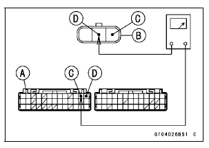
If the wiring is good, check the ECU for its ground and power supply (see ECU Power Supply Inspection in the Fuel System (DFI) chapter).
If the ground and power supply are good, replace the ECU (see ECU Removal/Installation in the Fuel System (DFI) chapter).
Test yourself
A quick Kawasaki Ninja ZX-10R quiz: every answer comes with an explanation and a link to the manual page.