Fan
Components and Component Location
Components
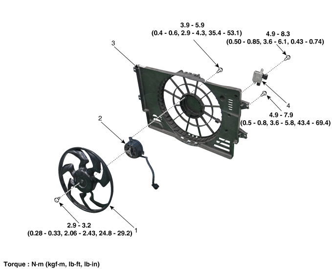
| 1. Cooling Fan 2. Fan Motor |
3. Cooling Fan Shroud 4. Cooling Fan Controller (PWM) |
Description and Operation
Description
The cooling fan operates in 2 steps (HIGH/LOW). The Engine Control Module (ECM) controls the cooling fan based on coolant temperature, vehicle speed and air conditioning operation.
Specifications
Specifications
| Items | Specification |
| Fan Type | Puller |
| Fan Speed Control Method | PWM |
| Air Flow Rate (m³/h) | 2050 - 8% min. |
| Fan Speed (rpm) | 2150 ± 8% |
| Current (A) | 23.3 +10% max. |
Circuit Diagrams
Wiring Diagram
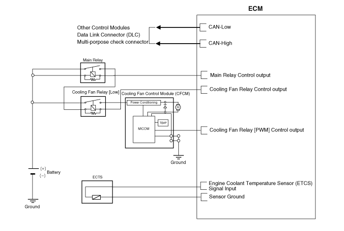
Repair Procedures
Removal and Installation
Disconnect the negative battery cable.
Remove the air cleaner assembly.
(See Intake and Exhaust System - Air Cleaner)
Remove the engine room cover.
(See Engine and Transaxle Assembly - Engine Compartment Cover)
Remove the air cleaner assembly.
(See Intake and Exhaust - Air Cleaner)
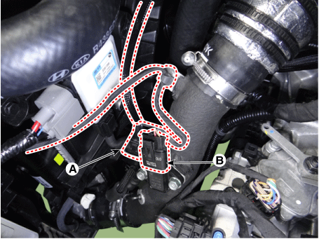
Disconnect the RCV solenoid valve connector (A) and the boost pressure sensor (BPS) connector (B).
Disconnect the intercooler outlet hose (A).
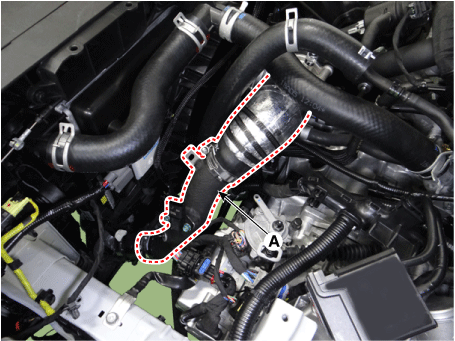
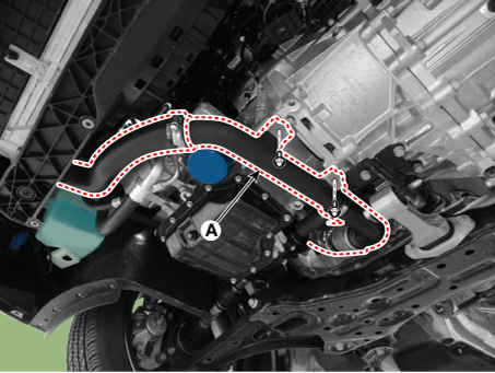
Remove the intake hose and intercooler pipe (A).
Tightening Torque
Hose clamp bolt:
4.9–6.9 N·m (0.5–0.7 kgf·m, 3.6–5.1 ft·lbf, 43.4–60.8 in·lbf)
(If equipped with a cap, tighten until the cap is removed.)
Pipe mounting bolt:
18,6–24 N·m
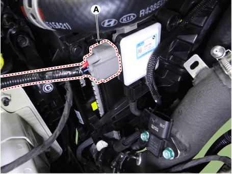
Disconnect the connector (A) of the cooling fan controller (PWM).
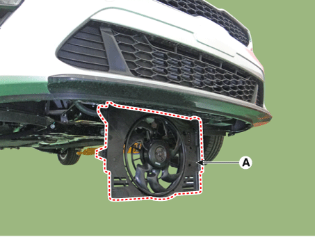
Remove the cooling fan assembly (A).
Tightening torque:
4.9–7.9 N·m (0.5–0.8 kgf·m, 3.6–5.8 ft·lbf, 43.4–69.4 in·lbf)
Cooling Fan Controller (PWM)
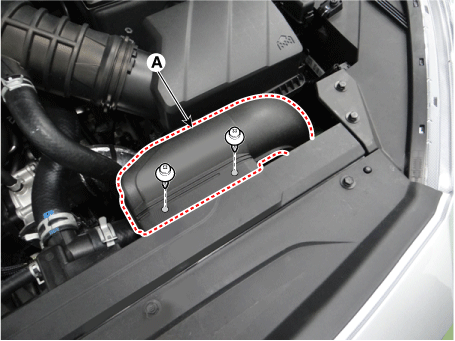
Remove the air duct (A).
Disconnect the cooling fan controller connector (A) and the cooling fan connector (B).
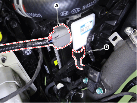
Remove the cooling fan controller (A).
Tightening torque:
4.9–8.3 N·m (0.50–0.85 kgf·m, 3.6–6.1 ft·lbf, 0.43–0.74 ft·lbf)
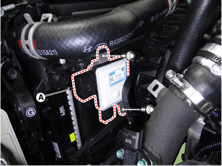
Install in the reverse order of removal.
Disassembly
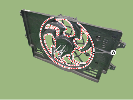
Remove the cooling fan (A) from the cooling fan assembly.
Tightening torque:
2.8–3.3 N·m (0.28–0.33 kgf·m, 2.06–2.43 ft·lbf, 24.3–28.6 in·lbf)
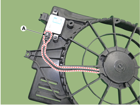
Disconnect the cooling fan motor connector (A).
Tightening torque:
2.8–3.3 N·m (0.28–0.33 kgf·m, 2.06–2.43 ft·lbf, 24.3–28.6 in·lbf)
Remove the fan motor (A) from the cooling fan shroud.
Tightening torque:
3.9–5.9 N·m (0.4–0.6 kgf·m, 2.9–4.3 ft·lbf, 35.4–53.1 in·lbf)
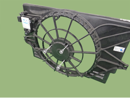
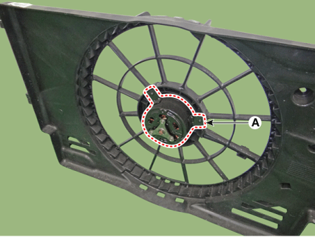
Installation is in the reverse order of removal.
Inspection
Blower motor
Disconnect the fan motor connector from the cooling fan controller.
Connect battery voltage to the "+" terminal and ground to the "-" terminal.
Make sure the cooling fan motor operates normally.
Test yourself
A quick Kia Forte BD quiz: every answer comes with an explanation and a link to the manual page.