Brake System
Service Data
Service Data
| Item | Specification |
| Master Cylinder | |
| Type | Single |
| Cylinder Inner Diameter | Ø 22.22 mm (0.875 in.) |
| Piston Stroke | 45 ± 1 mm (1.77 ± 0.039 in.) |
| Fluid Level Sensor | Provided |
| Brake booster | |
| Type | 10-inch Single |
| Booster Ratio | 8:1 |
| Front Disc Brake (15 inch) | |
| Type | Ventilated Disc |
| Rear Disc | 280 mm (11.0236 in.) |
| Disc thickness | 23 mm (0.9055 in.) |
| Disc Service Limit | 21 mm (0.8268 in.) |
| Cylinder Type | Single piston |
| Front Disc Brake (16 inch) | |
| Type | Ventilated Disc |
| Rear Disc | 305 mm (12.0079 in.) |
| Disc Thickness | 25.0 mm (0.9843 in.) |
| Disc Service Limit | 23.4 mm (0.9213 in.) |
| Cylinder Type | Single piston |
| Rear Disc Brake | |
| Type | Solid Disc |
| Disc O.D. | 262 mm (10.3149 in.) |
| Disc thickness | 10.0 mm (0.3937 in.) |
| Disc Service Limit | 8.4 mm (0.3307 in.) |
| Cylinder Type | Single piston |
| Drum Brake | |
| Type | Leading Trailing |
| Drum (Disc) ID | Ø 203.2 mm (8 in.) |
| Lining Thickness | 4.3 mm (0.1693 in) |
| Parking Brake | |
| Type | BIR (Ball in Ramp) |
| Activation | Lever |
Specifications (ABS)
| Part | Item | Standard Value | NOTE |
| HECU | System | 4-Channel 4-Sensor (Solenoid) | |
| Type | Motor, Integrated Valve Relay Type | ||
| Operating Voltage | 10 - 16 V | ||
| Operating Temperature | -40 to 120 °C | ||
| Engine Power | 230 W | ||
| Active Wheel Speed Sensor (ABS) | Supply Voltage | 4.5–20 V DC | |
| Low Output Current | 5.9–8.4 mA | ||
| High Output Current | 11.8–16.8 mA | ||
| Output range | 1 - 2500 Hz | ||
| Air gap | 0.4 - 1.0 mm |
Specifications (ESC)
| Part | Item | Standard Value | NOTE |
| HECU | System | 4-Channel 4-Sensor (Solenoid) | Full Control |
| Type | Motor, Integrated Valve Relay Type | (ABS, HAC, VSM) | |
| Operating Voltage | 10 - 16 V | ||
| Operating Temperature | -40 to 120 °C | ||
| Engine Power | 270 W | ||
| Active wheel speed sensor | Supply Voltage | 5–16 V DC | |
| Low Output Current | 5.9–8.4 mA | ||
| High Output Current | 11.8-16.8 mA | ||
| Output range | 0 - 2500 Hz | ||
| Tone wheel | 46 teeth | ||
| Air gap | 0.4 - 1.0 mm |
Service Standard
| Items | Standard Value |
| Brake pedal height | 183 mm (7.2047 in.) |
| Brake pedal full travel | 135 mm (5.3150 in.) |
| Stop Lamp Switch Clearance | 1.0–2.0 mm (0.04–0.08 in.) |
| Front Disc Brake Pad Thickness (15 inch) | 11.0 mm (0.4331 in.) |
| Front Disc Brake Pad Maximum Wear Limit (15 inch) | 2.0 mm (0.0787 in.) |
| Front Disc Brake Pad Thickness (16 inch) | 11.5 mm (0.4528 in.) |
| Front Disc Brake Pad Maximum Wear Limit (16 inch) | 2.0 mm (0.0787 in.) |
| Rear brake pad thickness | 9.0 mm (0.3543 in.) |
| Rear brake pad wear limit | 2.0 mm (0.0787 in.) |
Tightening Torque
Tightening torque
| Items | N·m | kgf·m | lbf·ft | |
| Master Cylinder to Brake Booster Nut | 9,8 - 15,7 | 1,0 - 1,6 | 7,2 - 11,6 | |
| Brake Booster to Brake Pedal Bracket Nut | 16,7 - 25,5 | 1,7 - 2,6 | 12,3 - 18,8 | |
| Brake Tube Flare Nuts at Master Cylinder | ABS | 12,7 - 16,7 | 1,3 - 1,7 | 9,4 - 12,3 |
| ESC | 18,6 - 22,6 | 1,9 - 2,3 | 13,7 - 16,6 | |
| HECU Bracket Mounting Bolts | 16,7 - 25,5 | 1,7 - 2,6 | 12,3 - 18,8 | |
| HECU Brake Tube Flare Nuts | ABS | 12,7 - 16,7 | 1,3 - 1,7 | 9,4 - 12,3 |
| ESC | 18,6 - 22,6 | 1,9 - 2,3 | 13,7 - 16,6 | |
| Front caliper guide rod bolts | 21,6 - 31,4 | 2,2 - 3,2 | 15,9 - 23,1 | |
| Rear caliper guide rod bolts | 21,6 - 31,4 | 2,2 - 3,2 | 15,9 - 23,1 | |
| Front caliper assembly to steering knuckle | 78,5 - 98,1 | 8,0 - 10,0 | 57,9 - 72,3 | |
| Rear Caliper Assembly with Rear Carrier | 78,5 - 98,1 | 8,0 - 10,0 | 57,9 - 72,3 | |
| Rear Caliper Assembly with Torsion Beam Axle | 63,7 - 73,5 | 6,5 - 7,5 | 47,0 - 54,2 | |
| Brake Hose to Caliper Bolt | 24,5 - 29,4 | 2,5 - 3,0 | 18,1 - 21,7 | |
| Brake Pedal Bracket Nuts | 16,7 - 25,5 | 1,7 - 2,6 | 12,3 - 18,8 | |
| Wheel speed sensor mounting bolt | 8,8 - 13,7 | 0,9 - 1,4 | 6,5 - 10,1 | |
Lubricants
Lubricants
| Items | Recommended | Quantity |
| Brake fluid | DOT 3 or DOT 4 | 505.5 ± 20 cc (30.85 ± 1.22 cu. in.) |
| Brake pedal bushing and bolt | Chassis grease | As required |
| Parking brake shoe and backing plate contact surface | Heat-resistant grease | As required |
Special Service Tools
Special Service Tools
| Tool Name/Number | Illustration | Description |
| Piston Expander 09581-2T100 |
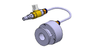 |
Front Disc Brake Piston Compression |
| SCC reflector 09964-C1100 |
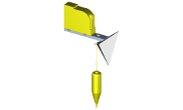 |
SCC Radar Alignment Reflector |
| Calibration beam 09964-C1200 |
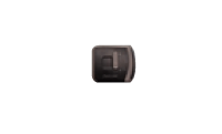 |
Laser for determining vehicle center. |
| Stand 09964-C1300 |
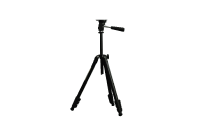 |
SCC reflector or vertical/horizontal laser support. |
| Sensor Cover Installer 09527-AL200 |
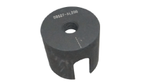 |
Used to install the wheel speed sensor cover (Sensor cover: Φ65.3) |
Troubleshooting
Troubleshooting
Symptom Table
Use the table below to find the cause of the problem. The numbers indicate the priority of the likely cause.
Check each part in order.
If necessary, replace these parts.
| Symptom | Possible Cause | Countermeasure |
| Low or Spongy Pedal | Brake System (Fluid Leak) | Repair |
| Brake System (Air Intrusion) | Bleeding Procedure | |
| Piston Seal (Worn or Damaged) | Replace | |
| Rear Brake Shoe Clearance (Incorrect Adjustment) | Adjust | |
| Master Cylinder (Malfunction) | Replace | |
| Brake Drag | Brake Pedal Free Travel (Minimum) | Adjust |
| Parking Brake Cable Length (Adjustment Problem) | Adjust | |
| Parking Brake Cable (Seized) | Repair | |
| Rear Brake Shoe Clearance (Adjustment Problem) | Adjust | |
| Lining and Backing Plate (Twisted or Cracked) | Replace | |
| Piston (Trapped) | Replace | |
| Piston (Seized) | Replace | |
| Anchor or Return Spring (Malfunction) | Replace | |
| Brake Booster (Vacuum Leak) | Repair | |
| Master Cylinder (Malfunction) | Replace | |
| Uneven Braking | Piston (Trapped) | Replace |
| Lining and Backing Plate (Oil Stains, Cracks or Warpage) | Replace | |
| Heavy Pedal Effort and Brake Problems | Brake System (Fluid Leak, Air Intrusion) | Perform the Bleeding Procedure |
| Brake Shoe or Lining (Worn) | Replace | |
| Pad Shim or Backing Plate (Cracked or Twisted) | Replace | |
| Rear Brake Shoe Clearance (Adjustment Problem) | Adjust | |
| Pad Shim or Backing Plate (Oil Stain) | Replace | |
| Pad Shim or Backing Plate (Slippery) | Replace | |
| Disc (Scored) | Replace | |
| Brake Booster (Vacuum Leak) | Repair | |
| Brake noise | Pad Shim or Backing Plate (Cracked or Twisted) | Replace |
| Loose Wheel Bolt and Caliper | Adjust | |
| Pad Sliding Problems (Uneven Pad Wear) | Replace | |
| Lining or Backing Plate (Dirty) | Cleaning | |
| Pad Shim or Backing Plate (Slippery) | Brake Pad Replacement | |
| Anchor or Return Spring (Malfunction) | Replace | |
| Brake Pad Shim (Damaged) | Replace | |
| Retaining Spring (Damaged) | Replace | |
| Foreign Object Caught Between Disc and Pad | Cleaning | |
| Corrosion on Disc | Brake Road Test and Cleaning * Remove friction corrosion by performing a brake road test |
|
| Cave-in Disc | Replace | |
| Brakes Not Fully Effective (at high driving speed) |
Brake Shoe or Lining (Worn) | Replace |
| Master Cylinder (Malfunction) | Replace | |
| Brake Vibration | Brake Booster (Vacuum Leak) | Repair |
| Pedal Free Separation | Adjust | |
| Master Cylinder (Malfunction) | Replace | |
| Master Cylinder Cap Damaged | Replace | |
| Brake Line Damaged | Replace | |
| Caliper Return Problem (while wheel rotates, check for noise) | Replace | |
| Converted Disc | Replace |
Brake Bleeding Procedures
Brake Bleeding
Make sure the brake fluid level in the reservoir is at the MAX (upper) level line.
Have someone slowly depress the brake pedal several times, then hold the pressure.
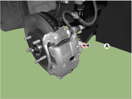
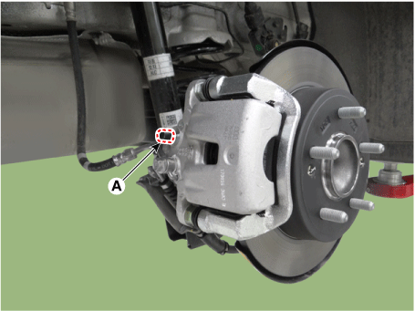
Loosen the right rear brake bleeder screw (A) to allow air to escape from the system. Then securely tighten the bleeder screw.
Front
Rear
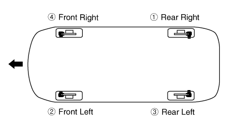
Repeat the procedure for each wheel in the sequence shown below until no more air bubbles appear in the fluid.
Fill the master cylinder reservoir to the MAX (upper) level mark.
ESC Brake Bleeding
This procedure must be performed to ensure proper air bleeding and filling of the ESC unit, brake lines, and master cylinder with brake fluid.
Remove the reservoir cap and fill the reservoir with brake fluid.
Recommended fluid: DOT 3 or DOT 4.
Connect a clear plastic tube to the wheel cylinder bleeder screw and insert the other end of the tube into a clear plastic bottle half-filled with brake fluid.
Connect the KDS to the data link connector located under the instrument panel.
Select and follow the instructions on the KDS screen.
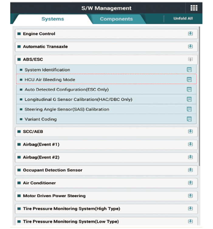
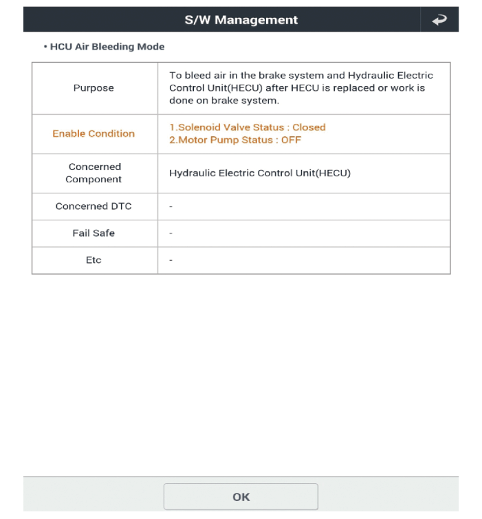
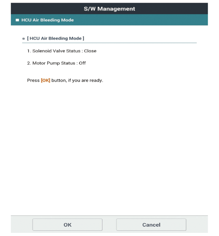
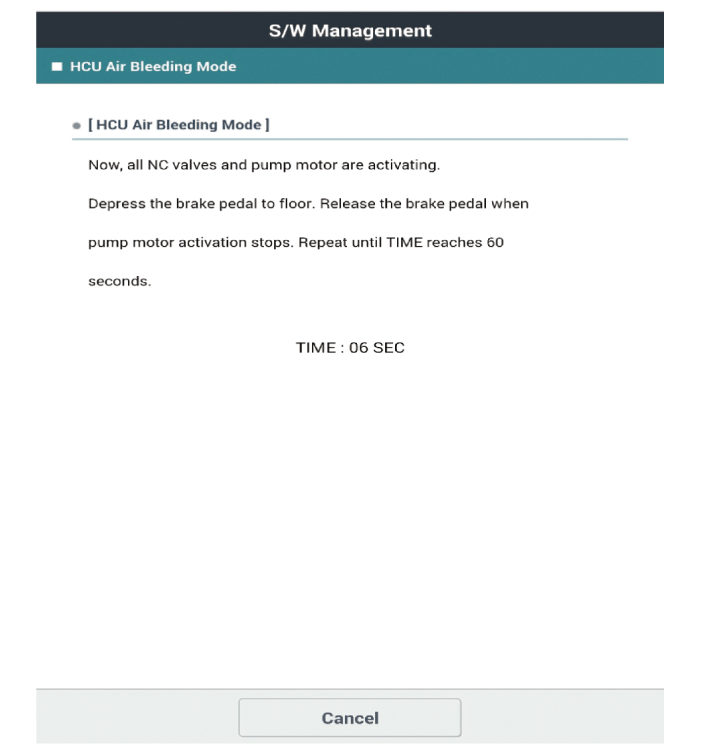
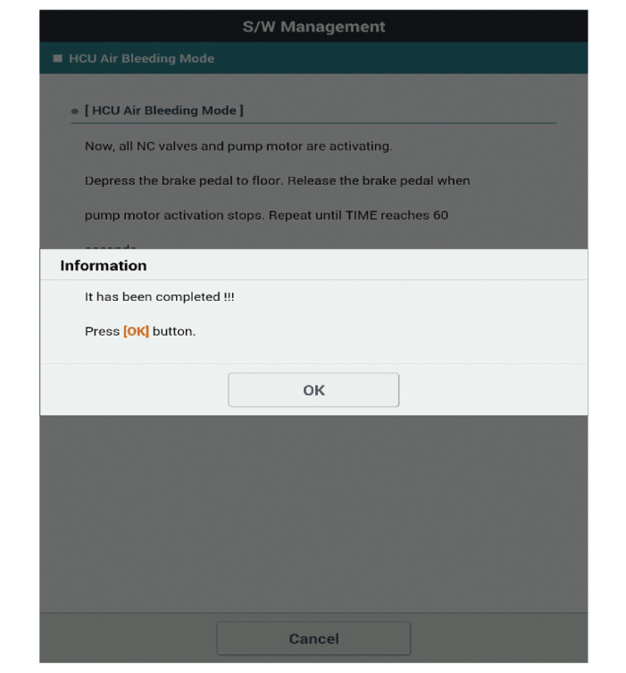
Depress the brake pedal several times, then loosen the bleeder screw to bleed air until fluid flows out without bubbles. Then close the bleeder screw (A).
Front
Rear
Repeat step 5 until there are no air bubbles in the fluid for each wheel.
Fill the master cylinder reservoir to the MAX (upper) level mark.
Test yourself
A quick Kia Forte BD quiz: every answer comes with an explanation and a link to the manual page.