Engine Mechanical System
Service Data
Specifications
| Description | Specifications | Limit | |
| General | |||
| Type | In-line, DOHC | ||
| Number of cylinders | 4 | ||
| Bore | 77 mm (3.0315 in.) | ||
| Hone | 85.44 mm (3.3638 in.) | ||
| Total Displacement | 1591 cc (97.09 cu in) | ||
| Compression ratio | 10,0 : 1 | ||
| Firing order | 1 - 3 - 4 - 2 | ||
| Valve Timing | |||
| Intake Valve | Opens | BTDC 10°/BTDC 40° | |
| Closes | ABTC 59°/ABDC 9° | ||
| Exhaust Valve | Opens | BBDC 36°/ABDC 4° | |
| Closes | BTDC 3°/BTDC 43° | ||
| Cylinder head cover | |||
| Gasket Surface Flatness | Overall flatness less than 0.05 mm (0.0020 in) Less than 0.02 mm (0.0008 in) per section 100 mm (3.9370 in) X 100 mm (3.9370 in) |
||
| Camshaft | |||
| Cam Lobe Height | Intake | 43.55 mm (1.7145 in) | |
| exhaust | 42.60 mm (1.6771 in) | ||
| Journal Outer Diameter (Intake, Exhaust) | 22.964–22.980 mm (0.9041–0.9047 in.) | ||
| Camshaft Cap Oil Clearance | 0.027–0.058 mm (0.0011–0.0023 in.) | 0.1 mm (0.0039 in.) | |
| End of Playback | 0.10–0.20 mm (0.0039–0.0079 in) | ||
| Valve | |||
| Valve Length | Intake | 93.15 mm (3.6673 in.) | |
| exhaust | 92.60 mm (3.6457 in.) | ||
| Stem Outer Diameter | Intake | 5.465–5.480 mm (0.2152–0.2157 in.) | |
| exhaust | 5.458–5.470 mm (0.2149–0.2154 in.) | ||
| Face Angle | 45,25° - 45,75° | ||
| Valve Head Margin Thickness | Intake | 1.10 mm (0.0433 in) | 0.8 mm (0.0315 in) |
| exhaust | 1.26 mm (0.0496 in.) | 1.0 mm (0.0394 in.) | |
| Valve Stem-to-Guide Clearance | Intake | 0.020–0.047 mm (0.0008–0.0019 in.) | 0.10 mm (0.0039 in.) |
| exhaust | 0.030–0.054 mm (0.0012–0.0021 in.) | 0.15 mm (0.0059 in.) | |
| Valve Guide | |||
| Length | Intake | 40.3–40.7 mm (1.5866–1.6024 in.) | |
| exhaust | 40.3–40.7 mm (1.5866–1.6024 in.) | ||
| Valve Spring | |||
| Free Length | 45.1 mm (1.7756 in.) | ||
| Out-of-Square | Less than 1.5° | ||
| Cylinder block | |||
| Cylinder Bore Diameter | 77.00–77.03 mm (3.0315–3.0327 in.) | ||
| Gasket Surface Flatness | Overall flatness less than 0.05 mm (0.0020 in) Less than 0.02 mm (0.0008 in) per section 100 mm (3.9370 in) X 100 mm (3.9370 in) |
||
| Piston | |||
| Piston Outer Diameter | 76.97–77.00 mm (3.0303–3.0315 in.) | ||
| Piston-to-Cylinder Clearance | 0.020–0.040 mm (0.0008–0.0016 in) | ||
| Ring Groove Width | No. 1 Ring Groove | 1.23–1.25 mm (0.0484–0.0492 in.) | 1.26 mm (0.0496 in.) |
| No. 2 Ring Groove | 1.53–1.55 mm (0.0602–0.0610 in.) | 1.26 mm (0.0496 in.) | |
| Oil Ring Groove | 2.01–2.03 mm (0.0791–0.0799 in.) | 2.05 mm (0.0807 in.) | |
| Piston Ring | |||
| Backlash | No. 1 Ring | 0.04–0.08 mm (0.0016–0.0031 in.) | 0.1 mm (0.0039 in.) |
| No. 2 Ring | 0.04–0.08 mm (0.0016–0.0031 in.) | 0.1 mm (0.0039 in.) | |
| Oil Ring | 0.02–0.06 mm (0.0008–0.0024 in.) | 0.2 mm (0.0079 in.) | |
| End Gap | No. 1 Ring | 0.14–0.24 mm (0.0055–0.0094 in.) | 0.30 mm (0.0118 in.) |
| No. 2 Ring | 0.30–0.45 mm (0.0118–0.0177 in.) | 0.50 mm (0.0197 in.) | |
| Oil Ring | 0.20–0.40 mm (0.0079–0.0157 in.) | 0.80 mm (0.0315 in.) | |
| Piston pin | |||
| Piston Pin Outer Diameter | 19.997–20.000 mm (0.7872–0.7874 in.) | ||
| Piston Pin Bore Inner Diameter | 20.004–20.009 mm (0.7875–0.7878 in.) | ||
| Piston Pin Bore Clearance | 0.004–0.012 mm (0.0001–0.0005 in.) | ||
| Connecting Rod Small End Bore Inner Diameter | 20.005–20.011 mm (0.7876–0.7878 in) | ||
| Connecting Rod | |||
| Connecting Rod Big End Inner Diameter | 45.000–45.018 mm (1.7717–1.7724 in.) | ||
| Connecting Rod Bearing Oil Clearance | 0.030–0.050 mm (0.0012–0.0020 in.) | 0.060 mm (0.0024 in.) | |
| Backlash | 0.10–0.25 mm (0.0039–0.0098 in.) | 0.35 mm (0.0138 in.) | |
| Crankshaft | |||
| Main Bearing Oil Clearance | № 1, 2, 3, 4, 5 | 0.020–0.041 mm (0.0009–0.0016 in) | 0.05 mm (0.0020 in.) |
| End of Playback | 0.05–0.25 mm (0.0020–0.0098 in.) | 0.3 mm (0.0118 in.) | |
| Cooling System | |||
| Cooling Method | Forced circulation with cooling fan | ||
| Coolant Capacity | Approximately 6.5 L (1.72 US gal, 6.87 US qt, 5.72 Imp qt) | ||
| Thermostat | Type | Wax Pellet Type | |
| Opening temperature | 82 ± 1,5 °C | ||
| Full Open Temperature | 95°C (203°F) | ||
| Radiator Cap | Main Valve Opening Pressure | 93.16 - 122.58 kPa (0.95–1.25 kgf/cm², 13.51–17.78 psi) |
|
| Vacuum Valve Opening Pressure | MAX. 6.86 kPa (0.07 kgf/cm², 1.00 psi) | ||
| Engine coolant temperature sensor | |||
| Type | Thermistor type | ||
| Resistance | 20°C (68°F) | 2.45±0.14 kΩ | |
| 80°C (176°F) | 0.3222 kΩ | ||
Tightening Torque
Tightening Torque
| Item | Quantity | N·m | kgf·m | lbf·ft | lbf·in |
| Engine Mounting | |||||
| Engine Mounting Bracket to Body Bolt | 3 | 49,0 - 36,7 | 5,0 - 6,5 | 36,2 - 47,0 | |
| Engine Mount Support Bracket to Engine Mount Insulator Nut | 1 | 88,3 - 107,9 | 9,0 - 11,0 | 65,1 - 79,6 | |
| Engine Mount Support Bracket to Engine Mount Bracket Bolt | 1 | 58,8 - 73,5 | 6,0 - 7,5 | 43,4 - 54,2 | |
| Engine Mount Support Bracket to Engine Mount Bracket Nut | 2 | 58,8 - 73,5 | 6,0 - 7,5 | 43,4 - 54,2 | |
| Transaxle Mounting Bracket to Body Bolt | 3 | 49,0 - 63,7 | 5,0 - 6,5 | 36,2 - 47,0 | |
| Transmission mount insulator to transmission mount bracket bolt | 2 | 98,0 - 117,7 | 10,0 - 12,5 | 72,3 - 86,8 | |
| Steering Rod Bracket to Subframe Bolt | 2 | 49,0 - 63,7 | 5,0 - 6,5 | 36,2 - 47,0 | |
| Strut insulator to strut mount bracket nut | 1 | 107,9 - 127,5 | 11,0 - 13,0 | 79,6 - 94,0 | |
| SYNC System | |||||
| Timing chain cover and oil pump assembly bolt (M6×20) | 10 | 9,8 - 11,8 | 1,0 - 1,2 | 7,2 - 8,7 | |
| Timing chain cover and oil pump assembly bolt (M6×38) | 2 | 9,8 - 11,8 | 1,0 - 1,2 | 7,2 - 8,7 | |
| Timing chain cover and oil pump assembly bolt (M6×70) | 1 | 9,8 - 11,8 | 1,0 - 1,2 | 7,2 - 8,7 | |
| Timing chain cover and oil pump assembly bolt (M8×22) | 3 | 18,6 - 23,5 | 1,9 - 2,4 | 13,7 - 17,4 | |
| Idler pulley bolt | 1 | 42,2 - 53,9 | 4,3 - 5,5 | 31,1 - 39,8 | |
| Timing Chain Tensioner Arm Bolt | 1 | 9,8 - 11,8 | 1,0 - 1,2 | 7,2 - 8,7 | |
| Timing Chain Guide Bolt | 2 | 9,8 - 11,8 | 1,0 - 1,2 | 7,2 - 8,7 | |
| Crankshaft Pulley Bolt | 1 | [46,1 - 51,9] + [38° - 42°] | [4,7–5,3] + [38°–42°] | [34,0–38,3] + [38°–42°] | |
| Engine mount bracket bolt | 4 | 29,4 - 41,1 | 3,0 - 4,2 | 21,6 - 30,3 | |
| Timing Chain Tensioner Bolt | 2 | 9,8 - 11,8 | 1,0 - 1,2 | 7,2 - 8,7 | |
| Cylinder head cover | |||||
| Ignition Coil Bolt | 4 | 9,8 - 11,8 | 1,0 - 1,2 | 7,2 - 8,7 | |
| Cylinder Head Cover Bolt | 19 | [3,9–5,9] + [7,8–9,8] | [0,4–0,6] + [0,8–1,0] | [2,9–4,3] + [5,8–7,2] | [34,5 - 52,2] + [69,0 - 86,7] |
| Camshaft Bearing Cap Bolt (M6) | 18 | 11,8 - 13,7 | 1,2 - 1,4 | 8,7 - 10,1 | |
| Camshaft bearing cap bolt (M8) | 4 | 18,6 - 22,6 | 1,9 - 2,3 | 13,7 - 16,6 | |
| Cylinder head bolt | 10 | [29,4] + [90°] + [90°] | [3,0] + [90°] + [90°] | [21,7] + [90°] + [90°] | |
| CVVT assembly bolt | 2 | 63,7 - 73,5 | 6,5 - 7,5 | 47,0 - 54,2 | |
| OCV (Oil Control Valve) bolt | 2 | 9,8 - 11,8 | 1,0 - 1,2 | 7,2 - 8,7 | |
| OCV (Oil Control Valve) exhaust valve adapter bolt | 2 | 9,8 - 11,8 | 1,0 - 1,2 | 7,2 - 8,7 | |
| Cylinder block | |||||
| Engine mount bracket bolt | 4 | 29,4 - 41,2 | 3,0 - 4,2 | 21,7 - 30,4 | |
| Ladder frame bolt | 13 | 18,6 - 23,5 | 1,9 - 2,4 | 13,7 - 17,4 | |
| Connecting rod cap bolt | 8 | [17,7–21,6] + [88–92°] | [1,8–2,2] + [88–92°] | [13,0–15,9] + [88–92°] | |
| Main Bearing Cap Bolt | 10 | [17,7–21,6] + [88–92°] | [1,8–2,2] + [88–92°] | [13,0–15,9] + [88–92°] | |
| Flywheel with external damper | 6 | 71,6 - 75,5 | 7,3 - 7,7 | 52,8 - 55,7 | |
| Lubrication System | |||||
| Oil Filter | 1 | 11,8 - 15,7 | 1,2 - 1,6 | 8,7 - 11,6 | |
| Oil Pan Bolt | 11 | 9,8 - 11,8 | 1,0 - 1,2 | 7,2 - 8,7 | |
| Oil Pan Drain Plug | 1 | 34,3 - 44,1 | 3,5 - 4,5 | 25,3 - 32,5 | |
| Oil screen nut | 2 | 24,5 - 31,3 | 2,5 - 3,2 | 18,0 - 23,1 | |
| Oil pressure sensor | 1 | 7,8 - 11,8 | 0,8 - 1,2 | 5,8 - 8,7 | |
| Oil level gauge assembly bolt | 1 | 9,8 - 11,8 | 1,0 - 1,2 | 7,2 - 8,7 | |
| Cooling System | |||||
| Water pump pulley bolt | 4 | 9,8 - 11,8 | 1,0 - 1,2 | 7,2 - 8,7 | |
| Water pump bolt | 5 | 9,8 - 11,8 | 1,0 - 1,2 | 7,2 - 8,7 | |
| Water temperature control assembly bolt | 3 | 9,8 - 11,8 | 1,0 - 1,2 | 7,2 - 8,7 | |
| Water inlet fitting nut | 2 | 18,6 - 23,5 | 1,9 - 2,4 | 13,7 - 17,4 | |
| Heater Pipe Mounting Bolt (M6) | 1 | 9,8 - 11,8 | 1,0 - 1,2 | 7,2 - 8,7 | |
| Heater Hose Mounting Nut | 2 | 9,8 - 11,8 | 1,0 - 1,2 | 7,2 - 8,7 | |
| Heater Pipe Mounting Bolt (M8) | 1 | 18,6 - 23,5 | 1,9 - 2,4 | 13,7 - 17,4 | |
| Engine Coolant Temperature Sensor (ECTS) | 1 | 29,4 - 39,2 | 3,0–4,0 | 21,7 - 28,9 | |
| Intake and Exhaust System | |||||
| Air intake hose clamp bolt | 2 | 2,9 - 4,9 | 0,3 - 0,5 | 2,2 - 3,6 | 26,0 - 43,4 |
| Air Cleaner Mounting Bolt | 3 | 3,9 - 5,9 | 0,4 - 0,6 | 2,8 - 4,3 | 34,7 - 52,1 |
| Intake manifold nut | 2 | 18,6 - 23,5 | 1,9 - 2,4 | 13,7 - 17,4 | |
| Turbocharger manifold module heat shield bolt | 3 | 9,8 - 11,8 | 1,0 - 1,2 | 7,2 - 8,7 | |
| Cylinder head cover heat shield bolt | 2 | 9,8 - 11,8 | 1,0 - 1,2 | 7,2 - 8,7 | |
| Turbocharger oil drain bolt | 2 | 9,8 - 11,8 | 1,0 - 1,2 | 7,2 - 8,7 | |
| Turbocharger oil drain pipe nut | 2 | 9,8 - 11,8 | 1,0 - 1,2 | 7,2 - 8,7 | |
| Turbocharger oil feed bolt | 2 | 9,8 - 11,8 | 1,0 - 1,2 | 7,2 - 8,7 | |
| Turbocharger oil feed pipe banjo bolt | 1 | 11,7 - 17,6 | 1,2 - 1,8 | 8,6 - 13,0 | |
| Turbocharger tube and hose bolt | 1 | 9,8 - 11,8 | 1,0 - 1,2 | 7,2 - 8,7 | |
| Turbocharger water pipe and hose banjo bolt | 2 | 26,4 - 32,3 | 2,7 - 3,3 | 19,5 - 23,8 | |
| Turbine housing module mounting nut | 9 | 35,3 - 41,1 | 3,6 - 4,2 | 26,0 - 30,3 | |
| Turbocharger Coupling Mounting Nut | 3 | 35,3 - 41,1 | 3,6 - 4,2 | 26,0 - 30,3 | |
| Intake Pipe Bracket Mounting Bolt (M8) | 6 | 18,6 - 23,5 | 1,9 - 2,4 | 13,7 - 17,3 | |
| Intake Pipe Bracket Mounting Bolt (M10) | 1 | 29,4 - 34,3 | 3,0 - 3,5 | 21,6 - 25,3 | |
| Intake Pipe Mounting Bolt | 1 | 29,4 - 34,3 | 3,0 - 3,5 | 21,6 - 25,3 | |
| Intake Pipe Mounting Nut | 2 | 35,3 - 41,1 | 3,6 - 4,2 | 26,0 - 30,3 | |
| Intercooler inlet pipe bolt | 2 | 19,6 - 26,4 | 2,0 - 2,7 | 14,4 - 19,5 | |
| Catalytic Converter Mounting Nut | 2 | 49,0 - 53,9 | 5,0 - 5,5 | 36,1 - 39,7 | |
| Muffler mounting nut | 4 | 39,2 - 58,8 | 4,0–6,0 | 28,9 - 43,4 | |
Lubricants
Lubricants
| Description | Specifications | Limit | |
| Engine Oil | |||
| Oil Capacity | General | 4.6 L - 4.9 L (1.21 - 1.29 US gal, 4.86 - 5.17 US qt, 4.04 - 4.30 Imp qt) | When replacing a short engine or engine assembly |
| Oil Baffle | 4.2 L (1.10 US gal, 4.43 US qt, 3.69 Imp qt) | ||
| Drain and Refill | 4.5 L (1.18 US gal, 4.75 US qt, 3.95 Imp qt) | Including oil filter | |
| Oil Grade | Recommended | - For Europe: ACEA C2/C3/5W-30 - For Middle East, India, Libya, Algeria, Morocco, Tunisia, Sudan, Egypt, Iran, etc.: ACEA A5/B5/5W-40 - For Central and South America: ACEA C2/C3/5W-30 |
|
| Allowable | - API SL or higher - ILSAC GF-3 or higher - ACEA A3 or higher - For SAE viscosity grades according to ambient temperature, refer to "Lubrication System." |
May be used if the recommended engine oil is not available | |
| Oil Pressure (at 1000 rpm) | 100 kPa (1.0 kgf/cm², 14.5 psi) or more | Engine Oil Temperature in Oil Pan: 110±2 °C | |
Special Service Tools
Special Service Tools
| Tool Name/Number | Illustration | Description |
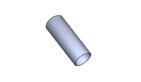
| Front Oil Seal Installer (Crankshaft) 09455-21200 |
 |
|
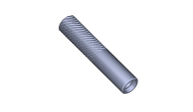
| Valve Stem Oil Seal Installer 09222-2B100 |
 |
|
| Valve Spring Compressor A: 09222-3K000 B: 09222-3K100 |
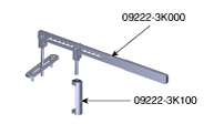 |
Used to remove/install intake or exhaust valve |
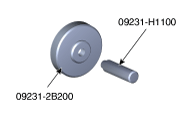
| Rear Crankshaft Oil Seal Installer A: 09231-2B200 B: 09231-H1100 |
 |
|
| Flywheel Stopper A: 09231-3N100 B: 09231-2B100 |
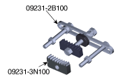 |
Used to prevent the flywheel from rotating when removing/installing the crankshaft pulley bolt. |
| Oil Pan Remover 09215-3C000 |
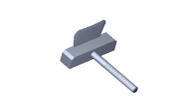 |
|
| Oil Filter Wrench 09263-2E000 |
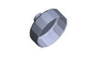 |
Used to remove/install the oil filter. |
| Radiator Cap Pressure Tester 0K253-G5100 |
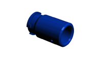 |
Used to check the radiator cap sealing pressure and coolant leakage. |
Compression Test
Compression Pressure Test
Make sure the engine oil has the correct viscosity and level, and that the battery is fully charged. Drive the vehicle until the engine reaches normal operating temperature. Turn the ignition switch to the OFF position.
Remove the engine cover.
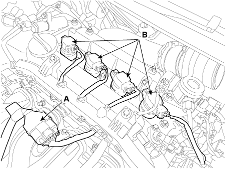
Disconnect the injector extension connector (A) and the ignition coil connectors (B).
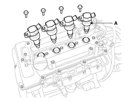
Remove the ignition coils (A).
Remove the spark plugs.
Using a 16 mm spark plug wrench, remove the 4 spark plugs.
Inspect the compression pressure in the cylinder.
Insert the compression gauge into the spark plug hole.
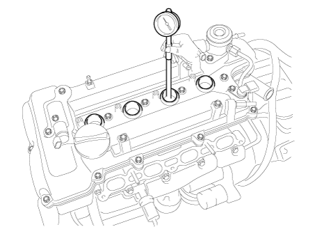
Set the throttle valve to the fully open position.
While cranking the engine, measure the compression pressure.
Repeat steps 1) through 3) for each cylinder.
Compression Pressure
Standard: 1225.83 kPa (12.5 kgf/cm², 177.79 psi) (200 - 250 rpm)
Minimum: 1078.73 kPa (11.0 kgf/cm², 156.46 psi)
Difference between each cylinder:
98 kPa (1.0 kgf/cm², 14 psi) or less
If compression in one or more cylinders is low, add a small amount of engine oil into the cylinder through the spark plug hole, and repeat steps 1) through 3) for the cylinders with low compression.
If adding oil improves compression, the piston rings and/or cylinder bore are likely worn or damaged.
If the pressure remains low, a valve may be stuck or improperly seated, or there may be a leak past the cylinder head gasket.
Install the spark plugs.
Tightening torque: 14.7–24 N·m
Install the ignition coil.
Tightening Torque: 9.8–11.8 N·m
Connect the injector extension connector and the ignition coil connectors.
Install the engine cover.
Troubleshooting
Troubleshooting
| Symptom | Suspected Area | Remedy |
| Engine misfire with abnormal internal low engine noise. | Flywheel loose or improperly installed. | Repair or replace the flywheel if necessary. |
| Worn piston rings. (Oil consumption may or may not cause engine misfire.) |
Inspect the cylinder for loss of compression. Repair or replace if necessary. |
|
| Crankshaft thrust bearings worn. | Replace the crankshaft and bearings if necessary. | |
| Engine misfire with abnormal valve train noise. | Valves stuck. (Carbon on the valve stem may cause the valve to close improperly.) |
Repair or replace if necessary. |
| Excessively worn or displaced timing chain. | Replace the timing chain and sprocket if necessary. | |
| Worn camshaft lobes. | Replace the camshaft and MLA. | |
| Engine misfire with coolant consumption. |
|
|
| Engine misfire with excessive oil consumption. | Wear of valves, valve guides and/or valve stem oil seals. | Repair or replace if necessary. |
| Worn piston rings. (Oil consumption may or may not cause engine misfire.) |
Check the cylinder for loss of compression. Repair or replace as necessary. |
|
| Engine noise on start-up that lasts only a few seconds. | Incorrect oil viscosity. | Drain the oil. Fill with oil of the correct viscosity. |
| Worn crankshaft thrust bearing. | Inspect the thrust bearing and crankshaft. Repair or replace as necessary. |
|
| Excessive engine noise regardless of engine speed. | Low oil pressure. | Repair or replace if necessary. |
| Broken valve spring. | Replace the valve spring. | |
| Worn or dirty valve lifters. | Replace the valve lifters. | |
| Stretched or broken timing chain and/or damaged sprocket teeth. | Replace the timing chain and sprockets. | |
| Worn timing chain tensioner, if equipped. | Replace the timing chain tensioner if necessary. | |
| Worn camshaft lobes. | Inspect the camshaft lobes. If necessary, replace the camshaft and valve lifters. |
|
| Worn valve guides or valve stems. | Inspect the valves and valve guides, then repair if necessary. | |
| Valves stuck. (Carbon on the valve stem or valve seat may cause the valve to remain open.) | Inspect the valves and valve guides, then repair if necessary. | |
| Low engine noise regardless of engine speed. | Low oil pressure. | Repair or replace damaged components as necessary. |
| Flywheel loose or damaged. | Repair or replace the flywheel. | |
| Damage to oil pan, contact with oil pump strainer. | Inspect the oil pan. Inspect the oil pump strainer. Repair or replace as necessary. |
|
| Oil pump strainer is loose, damaged, or clogged. | Inspect the oil pump strainer. Repair or replace as necessary. |
|
| Excessive piston-to-cylinder clearance. | Inspect the piston and cylinder bore. Repair as necessary. |
|
| Excessive clearance between piston pin and bore. | Inspect the piston, piston pin and connecting rod. Repair or replace as necessary. |
|
| Excessive connecting rod bearing clearance. | Inspect the following components and repair if necessary.
|
|
| Excessive crankshaft bearing clearance. | Inspect the following components and repair if necessary.
|
|
| Incorrect installation of piston, piston pin and connecting rod. | Make sure the piston pins and connecting rods are installed correctly. Repair as necessary. |
|
| Engine noise under load. | Low oil pressure. | Repair or replace if necessary. |
| Excessive connecting rod bearing clearance. | Inspect the following components and repair if necessary.
|
|
| Excessive crankshaft bearing clearance. | Inspect the following components and repair if necessary.
|
|
| Engine does not start (crankshaft does not rotate). | Hydraulic lock cylinder.
|
Remove the spark plugs and check for fluid. Inspect for a broken head gasket. Inspect the cylinder block or cylinder head for cracks. Inspect the fuel injector and/or fuel regulator for sticking. |
| Broken timing chain and/or timing chain sprocket. | Inspect the timing chain and sprockets. Repair as necessary. |
|
Foreign object in the cylinder.
|
Inspect the cylinder for damaged components and/or foreign material. Repair or replace as necessary. |
|
| Seized crankshaft or connecting rod bearings. | Inspect the crankshaft and connecting rod bearing. Repair or replace as necessary. |
|
| Bent or broken connecting rod. | Inspect the connecting rods. Repair or replace as necessary. |
|
| Broken crankshaft. | Inspect the crankshaft. Repair or replace as necessary. |
Test yourself
A quick Kia Forte BD quiz: every answer comes with an explanation and a link to the manual page.