Restraints
General Safety Information and Precautions
Precautions
General Precautions
Carefully read the following precautions before servicing the airbag system.
Follow the instructions in this manual, otherwise the airbags may deploy unintentionally and cause damage or injury.
Except when inspecting the electrical system, always turn the ignition OFF and disconnect the negative battery cable, then wait at least three minutes before starting work.
Use replacement parts manufactured to the same standards as genuine parts and of good quality.
Do not install used SRS parts from another vehicle. Use only new parts when repairing the SRS.
Carefully inspect any SRS part before installation. Do not install any part showing signs of dropping or mishandling, such as dents, cracks, or deformation.
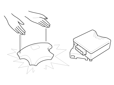
Before removing any SRSCM component (including disconnecting connectors), always disconnect the SRSCM connector.
Airbag Handling and Storage
Do not disassemble the airbags; they have no serviceable parts. Once an airbag has deployed, it cannot be repaired or reused.
For temporary storage of the airbag during service, observe the following precautions.
Store the removed airbag with the pad facing up.
Do not allow oil, grease, detergents, or water to contact the airbag assembly to prevent damage.
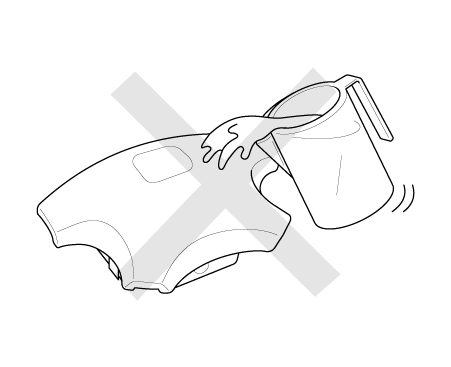
Store the removed airbag on a secure, flat surface away from heat sources (above 85 °C/185 °F).
Never perform electrical tests on airbags, such as measuring resistance.
Keep away from the airbag assembly during removal, inspection, or replacement.
Refer to the disposal procedures for a deployed or damaged airbag.
Be careful not to strike the SRS unit or the side impact sensors or front impact sensors when turning the ignition on. Turn the ignition off and wait at least three minutes before starting work.
During installation or replacement, be careful not to strike the area around the SRS unit and the side impact sensors and front impact sensors with a wrench, hammer, etc. The airbags may deploy unintentionally and cause damage or injury.
Replace the front airbag module, SRSCM, and FIS when the front airbag has deployed. Replace the airbag wiring harness if damaged. Replace the side airbag module, curtain airbag module, SRSCM, and SIS when the side airbag has deployed. Replace the airbag when the airbag wiring harness is damaged.
After a collision in which the airbags or side airbags did not deploy, inspect the SRS unit and side impact sensors for damage or deformation. If damaged, replace the SRS unit, front impact sensor, and/or side impact sensors.
Do not disassemble the SRS unit, front impact sensor, or side impact sensors.
Turn the ignition off, disconnect the negative battery cable, and wait at least three minutes before starting installation or replacement of the SRSCM.
Make sure the SRS unit, front impact sensor, and side impact sensors are securely fastened with the mounting bolts.
Do not spill water or oil on the SRS unit, front impact sensor, or side impact sensors, and protect them from dust.
Store the SRS unit, front impact sensor, and side impact sensors in a cool (15 - 25 °C/ 59 - 77 °F) and dry (30 - 80 % relative humidity, no moisture) area.
Connection Precautions
SRS wiring can be identified by its special yellow outer covering. Follow the instructions described in this section.
Never attempt to modify, splice, or repair SRS wiring. If there is an open circuit or damage to the SRS wiring, replace the harness.
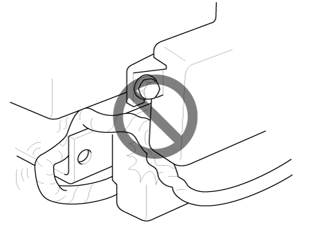
Make sure the harness wires are routed so they are not pinched or interfere with other parts.
Make sure all SRS ground points are clean and the grounds are securely fastened for optimal metal-to-metal contact. Poor grounding can cause intermittent problems that are difficult to diagnose.
Electrical Inspection Precautions
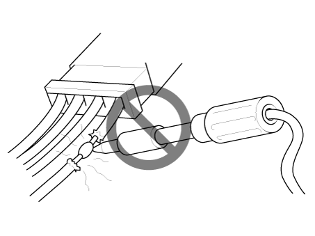
When using electrical test equipment, insert the tester probe from the wire side of the connector.
Do not insert the tester probe into the terminal side of the connector, and do not touch the connector terminals.
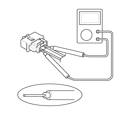
Use a U-shaped probe. Do not force the probe into the connector.
Use the specified service connectors for troubleshooting.
Using improper tools may cause an inspection error due to poor metal-to-metal contact.
Spring-Lock Connector
Some SRS connectors have a spring lock.
Airbag Connector
Disconnection
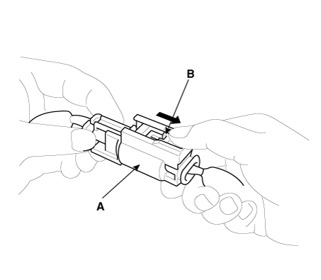
To release the lock, pull the spring-loaded sleeve (A) and slider (B) while holding the opposite half of the connector.
Separate the connector halves. Be sure to pull on the sleeve, not on the connector half.
Connection
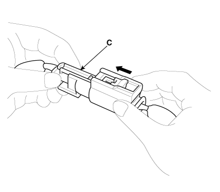
While holding both halves of the connector, press until the projection (C) on the coupling side clicks into place to lock the connector.
Abbreviation
| Abbreviation | Description |
| DAB | Driver Airbag |
| PAB | Passenger Airbag |
| SAB | Side Airbag |
| TAS | Curtain Airbag |
| SRSCM | Supplemental Restraint System (SRS) Control Module |
| FIS | Front Impact Sensor |
| P-SIS | Side Impact Pressure Sensor |
| G-SIS | Side Impact Gravity Sensor |
Service Data
Specification
| Item | Resistance (Ω) |
| Driver Airbag (DAB) | 1,7 - 2,3 |
| Passenger Airbag (PAB) | 1,7 - 2,3 |
| Side Airbag (SAB) | 1,8 - 2,4 |
| Curtain Airbag (CAB) | 1,7 - 2,3 |
| Seat Belt Pretensioner (BPT) | 1,7 - 2,3 |
| Seat Belt Buckle Switch (BS) | 1,7 - 2,3 |
| Emergency Fastening Device (EFD) | 1,7 - 2,3 |
Tightening Torque
Tightening torque
| Item | N·m | kgf·m | lbf·ft | lbf·in |
| Passenger Airbag (PAB) Bolt | 3,9 - 5,8 | 0,4 - 0,6 | 2,8 - 4,3 | 34,7 - 52,0 |
| Side Airbag (SAB) Nut | 5,8 - 7,8 | 0,6 - 0,8 | 4,3 - 5,7 | 52,0 - 69,4 |
| Curtain airbag (CAB) bolt | 7,8 - 11,7 | 0,8 - 1,2 | 5,7 - 8,6 | - |
| SRS Control Module (SRSCM) Nut | 6,96 - 7,25 | 0,71 - 0,74 | 5.13 - 5.35 | - |
| Frontal Impact Sensor (FIS) Bolt | 8,8 - 9,8 | 0,9 - 1,0 | 6,5 - 7,2 | - |
| Gravity Side Impact Sensor (G-SIS) Bolt | 8,8 - 9,8 | 0,9 - 1,0 | 6,5 - 7,2 | - |
Special Service Tools
Special Service Tools
| Tool Name/Number | Illustration | Description |
| Deployment Tool 0957A-34100A |
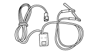 |
Used to deploy the airbag |
| Deployment Adapter 0K57A-3U100A |
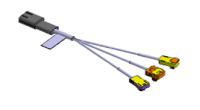 |
Used with the deployment tool (0957A-34100A) when deploying DAB, PAB, CAB, BPT |
| Deployment Adapter 0957A-2W100 |
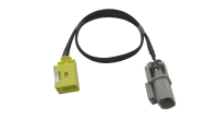 |
Used with the deployment tool (0957A-34100A) when deploying SAB |
| Dummy Unit 0957A-38200 |
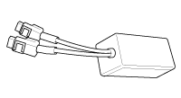 |
Airbag Wiring Harness Resistance Check Simulator |
| Dummy Adapter 0957A-2W200 |
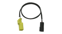 |
Used with the dummy (0957A-38200) when checking SAB resistance |
| Dummy Adapter 0957A-2G000 |
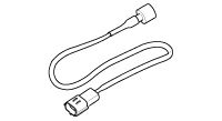 |
Used with the dummy (0957A-38200) when checking DAB, PAB, CAB, BPT resistance |
DAB: Driver Airbag
PAB: Passenger Airbag
SAB: Side Airbag
CAB: Curtain Airbag
BPT: Seat Belt Pretensioner
Description and Operation
Warning Lamp Activation
Warning Lamp Behavior After Ignition ON
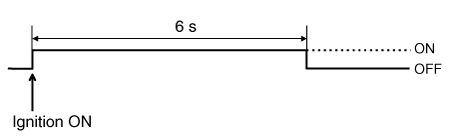
As soon as operating voltage is supplied to the SRSCM ignition input, the SRSCM activates the warning lamp for LED lamp check.
The lamp must illuminate for 6 seconds during the initialization phase and then turn off.
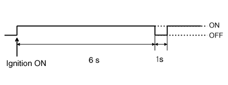
To warn the driver, the warning lamp must illuminate for 6 seconds and turn off for 1 second, then remain illuminated continuously after operating voltage is supplied if any active fault is present.
The active fault counter or historical fault counter is greater than or equal to 10.
The normal or historical fault counter is less than 10.
When the ignition is on in variant coding (EOL) mode, the airbag warning lamp will illuminate and flash at 1-second intervals until coding is completed.
If variant coding is performed correctly, the airbag warning lamp will illuminate for 6 seconds and then turn off. Otherwise, the airbag warning lamp will flash continuously at 1-second intervals.
If variant coding is performed correctly.
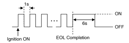
If variant coding is not completed.
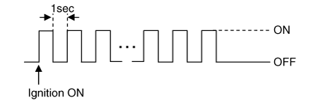
If an active fault is present in the airbag system or an internal SRSCM fault exists, variant coding (EOL) cannot be completed. In this case, after troubleshooting with KDS, perform the variant coding (EOL) procedure again.
Independent Activation of the SRSCM Warning Lamp
There are certain failure conditions in which the SRSCM cannot function and therefore cannot control the operation of the warning lamp. In these cases, the warning lamp is activated directly by the corresponding circuit, which operates independently of the SRSCM. These cases are:
Loss of SRSCM battery power: warning lamp remains on continuously.
Loss of internal operating voltage: warning lamp remains on continuously.
Loss of microprocessor operation: warning lamp remains on continuously.
SRSCM not connected: warning lamp remains on continuously.
Repair Procedures
Replacement of Components After Deployment
If the front airbags deployed after a collision, replace the following parts.
SRSCM
Deployed airbag(s)
Seat belt pretensioner(s)
Front impact sensors
Inspect the clock spring for heat damage.
If any damage is found, replace the clock spring.
If the side/curtain airbags have deployed after a collision, replace the following items.
SRSCM
Deployed airbag(s)
Side impact sensor(s) on the deployed side(s)
After completing all repairs to the vehicle, make sure the SRS airbag system is functioning properly.
Turn the ignition on; the SRS indicator should illuminate for approximately six seconds, then turn off.
Components and Component Location
Component Location
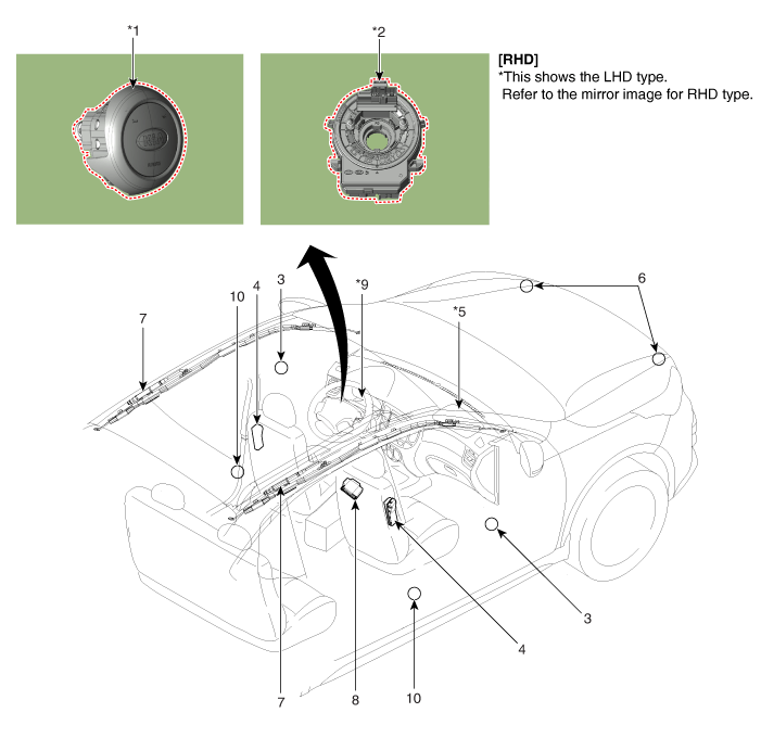
| 1. Driver Airbag (DAB) 2. Clock Spring 3. Pressure Side Impact Sensor (P-SIS) 4. Side Airbag (SAB) 5. Passenger Airbag (PAB) |
6. Frontal Impact Sensor (FIS) 7. Curtain Airbag (CAB) 8. Supplemental Restraint System Control Module (SRSCM) 9. Airbag Warning Lamp 10. Gravity Side Impact Sensor (G-SIS) |
Test yourself
A quick Kia Forte BD quiz: every answer comes with an explanation and a link to the manual page.