Fuel Pump Repair procedures
Inspection
[Fuel sender]
Turn the ignition switch OFF, and then remove battery (-) terminal.
Remove the fuel pump assembly.
Using an ohmmeter, measure the resistance between terminals 1 and 6 of sender connector (A) at each float level.
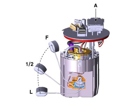
Pin No. Description 1 Fuel Sender (-) 2 Fuel pressure sensor (FPS) signal input 3 Fuel pressure sensor (FPS) ground 4 Ground (-) 5 CAN [Low] 6 Fuel Sender (+) 7 - 8 Fuel Pressure Sensor (FPS) Power [+5V] 9 CAN [High] 10 Battery Power (B+) Also check that the resistance changes smoothly when the float moves from "E" to "F".
Position Resistance (Ω) Capacity (L) E 298 - 305 3.0 1/2 80 - 82 22.5 F 14 - 16 44.1
Removal
Switch "OFF" the ignition and disconnect the negative (-) battery terminal.
Remove the rear seat cushion.
(Refer to Body - "Rear Seat Assembly")
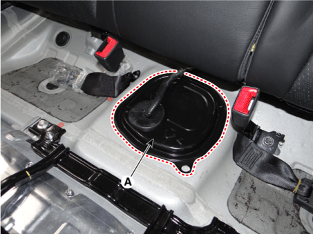
Fuel pump service cover (A).
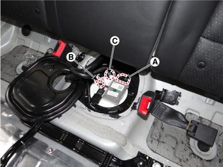
Remove the fuel pump control module connector (A).
Disconnect the fuel pressure sensor connector (B).
Disconnect the fuel feed tube quick-connector (C).
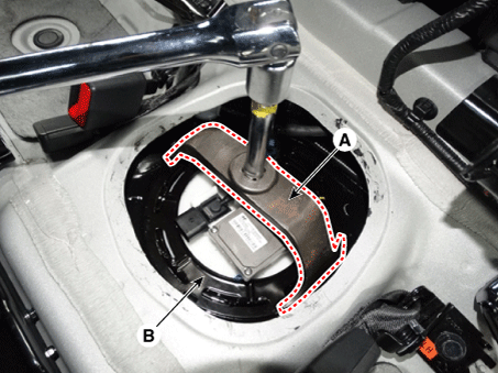
Remove the fuel pump plate cover (B) by using the special service tool (A) [SST NO.:09310-B8100].
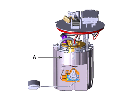
Remove the fuel pump (A).
Installation
Install in the reverse order of removal.